

Hello,
Today I was testing the fit of the Control Stick Bases to the Control Column and found a problem.
The first indication was a difference in the distance between the right and left VA-146 bearings of .020”.
Too much to account for powder coat roughness.
Then I inserted an AN4-37A and found it would not go thru.
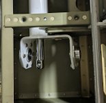
One of the ears on the control column is bent enough to be causing mis-alignment.
Clearly evident in the photos.

This shows the significant misalignment amount.
It is hard to measure but I estimate it’s close to 1/16”.

This shows the bolt inserted from the opposite direction.
It begins to go thru the bearing but binds up and stops about 1/8” in.

Not square.
I am inclined to remove the control column and attempt to straighten
it but am reluctant because of possible damage to the bearings.
Seems to me it may be best to replace the Control Column and the VA-146 bearings.
This a real bummer because of all the time I spent getting the assembly shimmed.
It’s working without any friction as instructed but it wasn’t easy.
Thanks,
Wayne
140736
Today I was testing the fit of the Control Stick Bases to the Control Column and found a problem.
The first indication was a difference in the distance between the right and left VA-146 bearings of .020”.
Too much to account for powder coat roughness.
Then I inserted an AN4-37A and found it would not go thru.
One of the ears on the control column is bent enough to be causing mis-alignment.
Clearly evident in the photos.
This shows the significant misalignment amount.
It is hard to measure but I estimate it’s close to 1/16”.
This shows the bolt inserted from the opposite direction.
It begins to go thru the bearing but binds up and stops about 1/8” in.
Not square.
I am inclined to remove the control column and attempt to straighten
it but am reluctant because of possible damage to the bearings.
Seems to me it may be best to replace the Control Column and the VA-146 bearings.
This a real bummer because of all the time I spent getting the assembly shimmed.
It’s working without any friction as instructed but it wasn’t easy.
Thanks,
Wayne
140736
 It was installed per the KAI before the side skins were installed which are now blocking the removal path.

")


