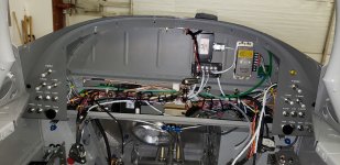
That is where you start. The design approach is to first divide the wiring world into what says in the plane when the panel is removed and what comes out with the panel.
Examples:
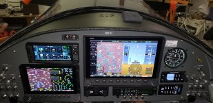
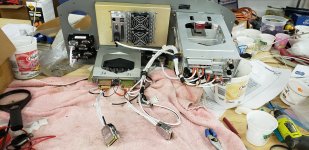
- The only breakers on the panel are for the GTN-650 (2) and the audio panel, plus a spare if needed in the future. These breakers get power via a molex plug. Three D connectors feed the GTN-650 and audio panel, and a connector for the GTN-650 to the ARINC module.
- The other breakers for stuff like the remote XPDR, both EFIS displays, remote Comm #2, ADS-b receiver an such get mounted on the panel are”side wings” and say in the plane. The EFIS displays and such disconnect via provided D connector and such.
- Also on the side wings other stuff that stays in the panel include both Master switches, both avionics switches, both ignition switches and such.
- All the other non panel switches are on the right side fuselage panel. Stuff like landing lights, alternator VR, pitot heat, boost pump and such.
Attached photos show most of this.
For a retro fit, if you have stuff already on the panel side wings (like a vent, clock, g-meter, etc.) do not try to replace the wings as it will mess up your paint job. Use some 0.032” or so aluminum and make an overlay of the existing side wings. Drill new holes for switches and breakers. I did this on an RV-8A and you cannot tell it was done once the panel is in.
Carl