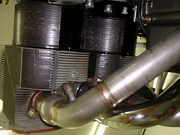
Lycoming cylinders have a classic baffle problem. I don't know if anyone else has taken this particular approach to solving it (lots of ways to skin a cat), but maybe the pictures will help the new guys understand the issue.
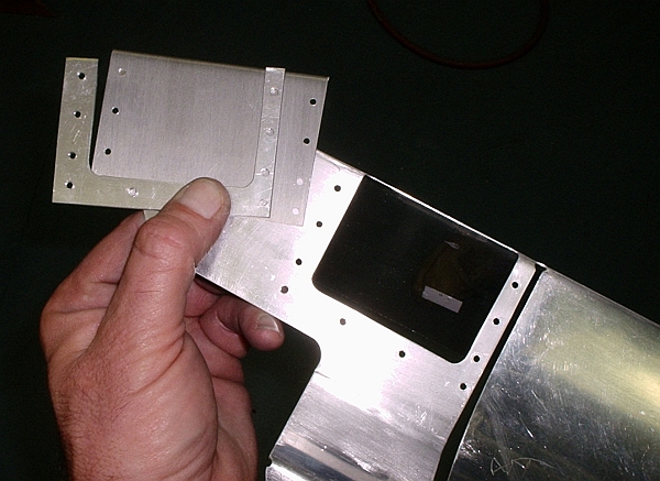
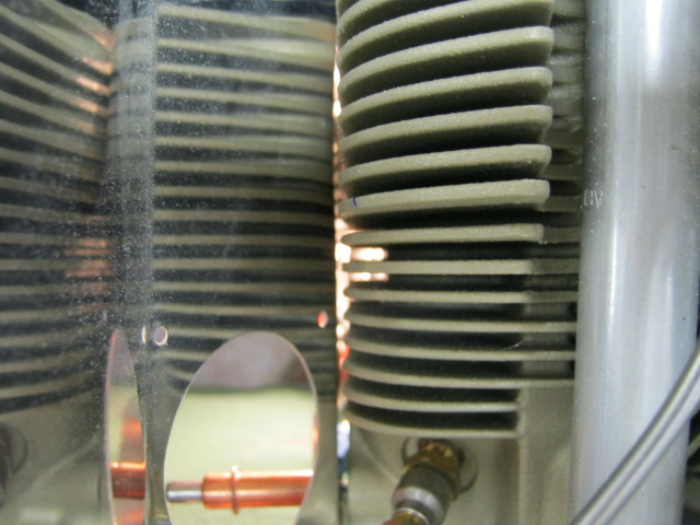
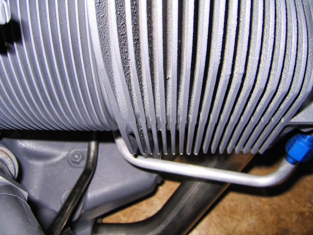
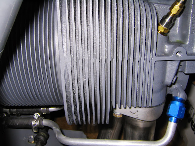
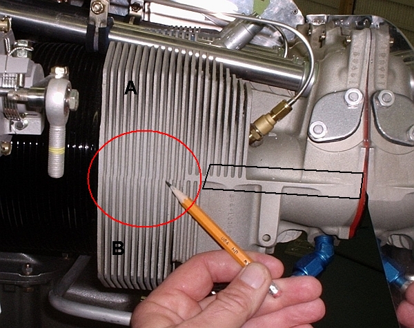
Here's the root of the problem. The intake side of the head has no fin depth in the area indicated by the pencil. but standard baffles for the left front and right rear cylinders place a plate directly against this area. There is plenty of air at "A", but there is no way for air to circulate down to area "B"
Details:
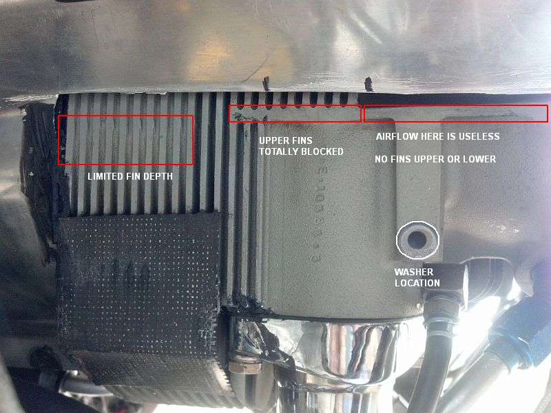
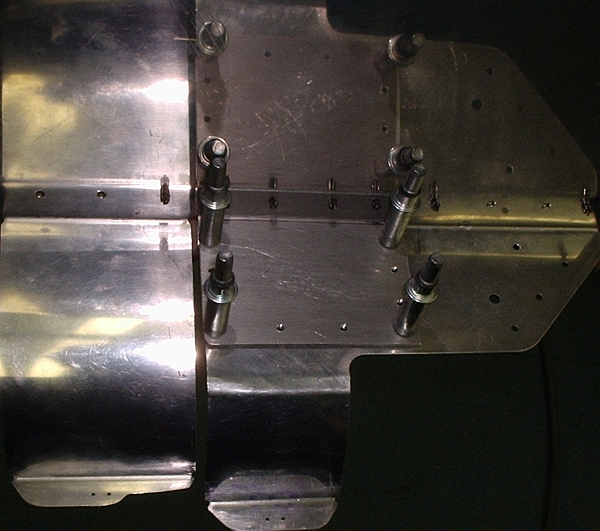
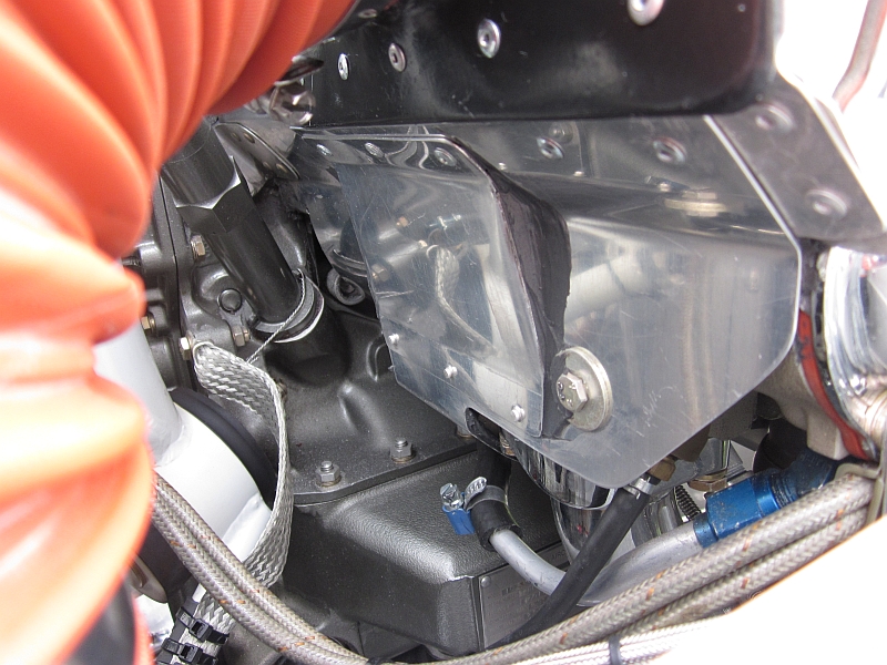
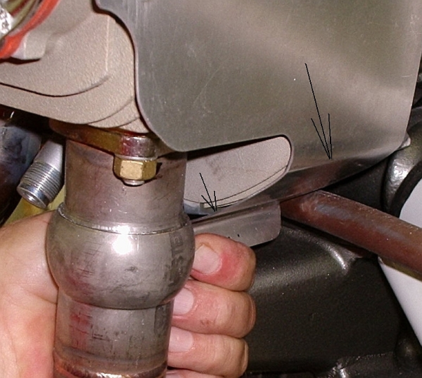
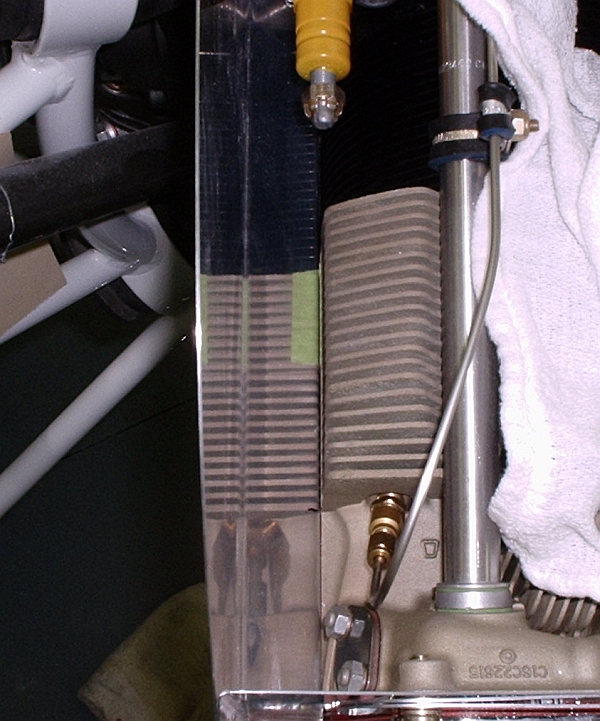
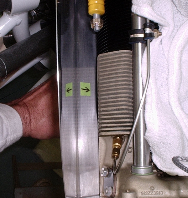
Here's the standard baffle (right rear) against the head. Flow to the lower fins and baffle wrap is blocked by the zero-depth fin area identified by the green tape. The standard "cure" is to place a washer or some other spacer between the head and the baffle, but that opens a gap along the entire length of the baffle plate.....in particular the area outlined in a black rectangle above. Any air sneaking past the area in the rectangle is pure leakage.
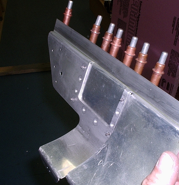
It is quite easy to hammerform a small duct of sorts in the baffle plate. The "duct" is nothing more than a fancy dent knocked in the sheet.
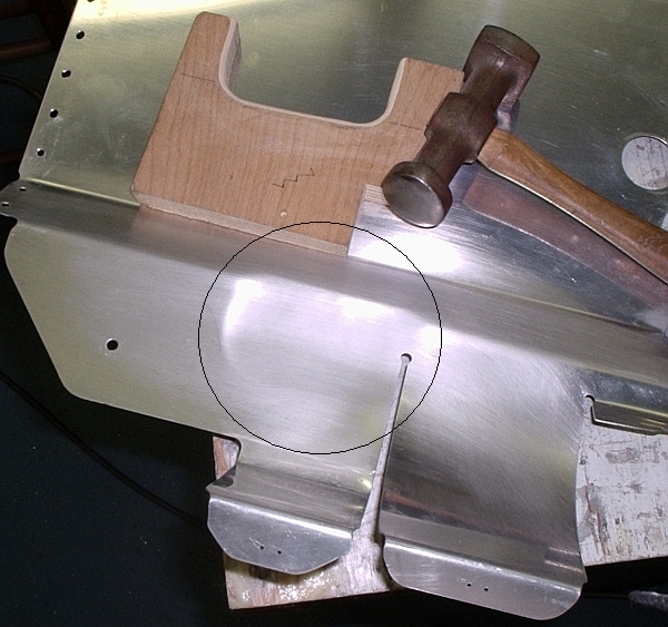
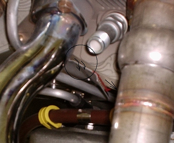
The result is a passage to bypass the no-depth fin area (arrow). Now air can flow down the back of the head and pass in between the lower fins where you have a baffle wrap. The reminder of the baffle plate is not spaced away from the head and cylinder, reducing undesired leakage. Any air not passing between fins is pure drag; it didn't do any cooling work.
Not all builders have metal forming hammers, or may not want to try beating on an expensive baffle part as their first metal forming experience. I'll do the left front baffle using an alternate method and get it up here soon.
Have fun.
----->>>>POSTSCRIPT: See posts 24 and 25
Here's the root of the problem. The intake side of the head has no fin depth in the area indicated by the pencil. but standard baffles for the left front and right rear cylinders place a plate directly against this area. There is plenty of air at "A", but there is no way for air to circulate down to area "B"
Details:
Here's the standard baffle (right rear) against the head. Flow to the lower fins and baffle wrap is blocked by the zero-depth fin area identified by the green tape. The standard "cure" is to place a washer or some other spacer between the head and the baffle, but that opens a gap along the entire length of the baffle plate.....in particular the area outlined in a black rectangle above. Any air sneaking past the area in the rectangle is pure leakage.
It is quite easy to hammerform a small duct of sorts in the baffle plate. The "duct" is nothing more than a fancy dent knocked in the sheet.
The result is a passage to bypass the no-depth fin area (arrow). Now air can flow down the back of the head and pass in between the lower fins where you have a baffle wrap. The reminder of the baffle plate is not spaced away from the head and cylinder, reducing undesired leakage. Any air not passing between fins is pure drag; it didn't do any cooling work.
Not all builders have metal forming hammers, or may not want to try beating on an expensive baffle part as their first metal forming experience. I'll do the left front baffle using an alternate method and get it up here soon.
Have fun.
----->>>>POSTSCRIPT: See posts 24 and 25
Last edited:
")