I haven't even flown yet, but my Vans-supplied master solenoid failed the other day when I was about to load some software updates to my Dynon Skyview system. You could hear the click, but there wasn't any current coming out of the solenoid. The Vans unit had been failing intermittently for some time, so this wasn't a huge surprise. So, I thought this is a good time to buy a new, quality solenoid and I went ahead and spent over $60.00 on a new Lamar X61-0028 from ACS.
While waiting on some resin to cure today, I thought I'd install the new solenoid, which I proceeded to do. When I hit the master switch, nothing happened...I'm thinking huh? So, I removed the solenoid and bench tested it, which I should have done in the first place. It failed and I am having a hard time believing that a new, out of the box unit wouldn't work, and so I am putting this out for comments.
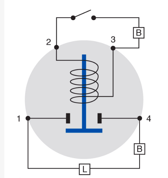
Here's a photo of the unit:

A is connected to the + terminal of the battery, B is connected to terminal A with a 20 ga wire, C is connected to the master switch (which is connected to ground when the switch is turned on) and D is connected to the load. As I understand it, this is a conventional set up.
When I had the unit on my bench, I connected A to the positive terminal of my 12v power supply, and I connected the - terminal of the power supply to C, and a click was heard. When I tested the dc volts between A and C, I got 13.6 volts, which is exactly what I would expect. When I tested the dc volts between C and D, I should have gotten 13.6 volts, but I got nothing. When I checked continuity between A and D, I got nothing where I should have gotten continuity.
I'm no electrical wizard, but my understanding is that the B and C terminals simply activate the solenoid, which just bridges terminals A and D. Stone simple.
So, am I missing something (wouldn't be the first time) or did I buy a bum unit?
While waiting on some resin to cure today, I thought I'd install the new solenoid, which I proceeded to do. When I hit the master switch, nothing happened...I'm thinking huh? So, I removed the solenoid and bench tested it, which I should have done in the first place. It failed and I am having a hard time believing that a new, out of the box unit wouldn't work, and so I am putting this out for comments.
Here's a photo of the unit:
A is connected to the + terminal of the battery, B is connected to terminal A with a 20 ga wire, C is connected to the master switch (which is connected to ground when the switch is turned on) and D is connected to the load. As I understand it, this is a conventional set up.
When I had the unit on my bench, I connected A to the positive terminal of my 12v power supply, and I connected the - terminal of the power supply to C, and a click was heard. When I tested the dc volts between A and C, I got 13.6 volts, which is exactly what I would expect. When I tested the dc volts between C and D, I should have gotten 13.6 volts, but I got nothing. When I checked continuity between A and D, I got nothing where I should have gotten continuity.
I'm no electrical wizard, but my understanding is that the B and C terminals simply activate the solenoid, which just bridges terminals A and D. Stone simple.
So, am I missing something (wouldn't be the first time) or did I buy a bum unit?