Van's Air Force

The definitive Van's Aircraft support community! Buying, building or flying an RV? Join our exclusive family of mentors and enthusiasts!

Are 'Always On' Avionics a bad idea (Smoke in the Cockpit)

TASEsq

Well Known Member
Patron
I am planning my RV14 Electrical system for an electrically dependent engine - it will be IFR, so some items of avionics will be essential for all phases of flight.

The question is:
Is it a bad idea to have some avionics (such as the PFD) always powered on, even when the master is turned off (like in a smoke in the cockpit scenerio).

I am concerned that if i did have smoke in the cockpit, and it happened to be the PFD or a primary COM etc, that i could not de-power these devices with the normal "master off" approach. Similarly, these are really required to fly safely in IFR, so don't want to be in cloud and end up running only on the battery of the G5 and unable to get back down.

OR is this a non-issue that i shouldn't be concerned about? Would these items simlpy burn out their fuse is something internal started to smoke? (or impossible to know).

Some background:
I am planning to have:
- A main bus (32 position fuse block), which will power all the non-essential items, as well as the secondary power feeds to essential avionics.
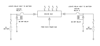
- An engine bus (20 position fuse block), which will power the EFI system.
- Another power distribution device for primary power to essential IFR avionics.

The question is:
- Is it a good idea to power the essential IFR flight instruments off this engine bus? (3rd page of the attached) or
- Have a second "Essential Bus" which is made up of traditional breakers / copper bus bars, to allow me to depower any or all of these essential items as required?

If so,
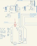
- Can this "essential bus" be powered directly off the main bus (2nd page of the attached) with a short feeder (aka the engine fuse block and traditional breakers physically next to each other), or
- Should this "essential bus" be fed from the appropriate contactors via direct feeds (1st page of the attached).

I also warmly welcome any additon feedback to V5356.2 of my proposed system which has been keeping me up at night! :)

Side note:
The indenendently fed essential bus, would allow me to potentially split the EFI components across 2 engine busses (potentially protecting against bus failure or shorts), however i am not sure how to approach injector power, which only have a single feed to them. This is a still outstanding concept if anyone has any thoughts in dual feeding EFI injectors.
 

Attachments

I can't speak to how other PFDs work but my AFS has a full-time power lead. The unit goes on with the master and has a 30 second timeout when the master is shut off. The timeout can be overridden with a button press so it ends up staying on with the master off. This is a built-in feature without any dual battery or bus shenanigans, although I do have a small backup battery for the EFIS.
EDIT: also I recommend having a way to easily pull power from the EFIS; in my case it's a pullable CB.
 
I asked the same question to the G3X team at Oshkosh last year, and said that they had no concerns with this power arrangement.
I will be having my G3X permanently powered once the master is on.
Make sure the flyback diodes are in place across the master, starter relays etc to take care of the back EMF voltage spikes.

Rob
 
I will be having my G3X permanently powered once the master is on.
The unit goes on with the master and has a 30 second timeout when the master is shut off.

I think this is normal behaviour for avionics - in these cases the units would shut down once the master went off (like in a cockpit smoke event).

What about if they stayed on when the master went off? (They would turn off when the ENGINE master goes off at the end of the flight).

If they are on a fuse I would have no way to turn them off in a cockpit smoke event - but this greatly simplifies the build. Otherwise, I think they need a seperate bus made with breakers, not fuses.
 
Similarly, these are really required to fly safely in IFR, so don't want to be in cloud and end up running only on the battery of the G5 and unable to get back down.
I might be wrong, but I thought the internal battery of the G5 will outlast the fuel supply of an RV.
 
IMHO nothing should be on the engine bus that is not required to run the engine. A PFD is not at the same level of criticality. When stuff hits the fan, you want the ability to disconnect everything but what is necessary to keep the engine running. This assumes backups like a G5.

If you want something like an essential buss, it cannot be fed from downstream of the master contactor, otherwise it is just a branch oh the main bus. In theory, you want the ability to progressively shut things down in case of problems.
 
Last edited:
Has anyone ever had a modern avionics unit smoke? By modern, I mean one made within the past 25 years?
It is generally not just smoking devices that you need to deal with. It is shorts in the wiring that is the concern. When you have a short, the insulation burns and creates the smoke. If it doesn't flow enough current to pop the breaker, shutting down the bus is the only way to stop it. Don't forget that there are at least two wire feeds that are not fused. Modern wiring is no less likely to short than wire from 25 years ago. It is typically caused by chaffing.
 
Last edited:
It is generally not just smoking devices that you need to deal with. It is shorts in the wiring that is the concern. When you have a short, the insulation burns and creates the smoke. If it doesn't flow enough current to pop the breaker, shutting down the bus is the only way to stop it. Don't forget that there are at least two wire feeds that are not fused.
Which ones are you referring to?

I had midi fuses on all of the feeds into the cockpit.
 
I may not be following completely here, but if your PFD is always powered on, then how do you turn it off even on the ground? Would you just power it off via the physical buttons after shutdown? If so, I'd find out for sure whether or not it uses any power even when it is "off" so you don't slowly drain your battery.

From a safety perspective:
  • If you smell electrical fire and turn off both batteries, what if the PFD is the source of the issue? If I had to choose between stopping an electrical fire and keeping my PFD, I'll choose to stop the fire every time, even in hard IMC (with a G5 and an iPad)
  • In an accident, the more hot wires running around your aircraft, the more chance there is for a spark to ignite fuel, so ideally you'd want to de-power everything before an off-airport landing.
I have done a number of practice approaches with my G5 plus ForeFlight and am pretty confident that I can safely land the plane in IMC. Would I want to do it in Low IFR and a short runway? No... but I'd still prefer it over fire.
 
Which ones are you referring to?

I had midi fuses on all of the feeds into the cockpit.
The feeds from the alt and battery to your primary fuse or breaker distribution point is unprotected, assuming you follow best practices.
 
The fewer switches the better. When things go wrong and the pilot's
life is in danger, she won't remember what all of those switches are for.
The Monkworkz B lead is attached to the wrong side of the 30amp fuse.
If that 10AWG wire shorts to ground, battery current will melt it.
Consider using fuselinks instead of MIDI 30 amp fuses.
In the top drawing, note that current can flow from the 60amp alternator to the engine bus to the left side bus bar to the ESS bus. Likewise, current can flow from the 60amp alternator to the ESS bus to left side bus bar to the engine bus.
Overvoltage can damage engine electrical components. There needs to be overvoltage protection.
Engine Bus.png
 

Attachments

  • Engine Bus.png
    Engine Bus.png
    4.6 KB · Views: 31
Last edited:
Has anyone ever had a modern avionics unit smoke? By modern, I mean one made within the past 25 years?
You should clarify that to exclude hooking the power backward during install - I've seen that happen to a couple people!
 
The feeds from the alt and battery to your primary fuse or breaker distribution point is unprotected, assuming you follow best practices.
They are protected by midi fuses FWF. Definitely not unprotected.

I may not be following completely here, but if your PFD is always powered on, then how do you turn it off even on the ground?
Have a look at post #1. The diagram helps. It is always powered on *when the engine is running* - so long as the engine bus has power, then the PFD would have power. The questions is, does it need a physical breaker I can manually use to turn it off in an emergency, or is the likelihood of this being a cause of smoke zero.? Hope the question makes sense.

The Monkworkz B lead is attached to the wrong side of the 30amp fuse.
If that 10AWG wire shorts to ground, battery current will melt it.
Consider using fuselinks instead of MIDI 30 amp fuses.
Great! you are right. I missed that. I drew it to the other side of the existing midi, then realised that if the monkworkz b lead shorts, it will also take out the feed to the engine bus.
IMG_0149.jpeg

Whereas, if it has its own midi, then all the battery does is open that midi and the feed to the engine bus remains.
IMG_0150.jpeg

The comments about fuse links is noted. I need to think about this some more. I see that b&c sells fuse link kits, but the biggest they had was 16-20. So I assumed I needed to use midis. What is best practice here for a #10 wire? I could solder a #14 but then this is a weak point subject to vibration perhaps? Stein sells a 10-12 yellow butt splice - I don’t know if a doubled over #14 wire would work in this. I’ll have to see if I have one in the shed.

Also, is 3 ring terminals on the post of the contactor ok? without the midis I would not have to stack up ring terminals on the post of the contactor.

Appreciate everyone’s help!
 
Not only is there a danger of reverse polarity during installation, but also when jump starting or even when using a bench power supply. There is a simple solution to this problem. Just install a fuse between the battery contactor and the master switch. One might say that no fuse is needed because that wire gets grounded. But that fuse will blow if the polarity is reversed and protect expensive avionics. The reason the fuse will blow is because with reverse polarity, the arc suppression diode will be a short circuit. Hopefully the fuse blows before the battery contactor is pulled in. I put a 5 amp fuse on the drawing below, but a 3 amp fuse might be big enough and will blow quicker.

Master SW.png
 
Last edited:
Not only is there a danger of reverse polarity during installation, but also when jump starting or even when using a bench power supply. There is a simple solution to this problem. Just install a fuse between the battery contactor and the master switch. One might say that no fuse is needed because that wire gets grounded. But that fuse will blow if the polarity is reversed and protect expensive avionics. The reason the fuse will blow is because with reverse polarity, the arc suppression diode will be a short circuit. Hopefully the fuse blows before the battery contactor is pulled in. I put a 5 amp fuse on the drawing below, but a 3 amp fuse might be big enough and will blow quicker.

View attachment 81951
Best idea I’ve seen in a long time!!

Carl
 
For the hive mind…

I folded over a #14 and it fits into a yellow butt splice - just. So a fuseable link arrangement could work for a #10 feeder.
IMG_5075.jpeg

Regarding a #10 (#14) fusible link:

Looking at Wikipedia (the aviation section) it says a #14 copper wire will melt at 166 amps.

Looking at a curve for a 30amp midi, it says 166amps would blow the fuse in one second.

I don’t really know how many amps would occur in a short of course, so the midi could blow quicker than this?

Because I had nothing better to do on a Sunday than scare the crap out of myself, I can tell you a shorted #14 wire will start to smoke in 3.84 seconds, lose its insulation in 5.68 seconds and finally burn through removing the short in 12.13 seconds. It obviously had more than 166 amps.


The midi fuse holders are $14 each, and a midi fuse is $6, so for $20 per circuit is it better it to have much faster protection (and replaceable)?

Edit: to add:
If it were an EarthX battery installation, I think the bms is around 2 seconds. Using a 12 sec fusible link might mean the ban disconnects the battery? Whereas, a midi would possibly flow before the bms disconnected?
 

Attachments

  • IMG_5078.png
    IMG_5078.png
    3.3 MB · Views: 19
  • IMG_5079.png
    IMG_5079.png
    2.1 MB · Views: 19
Last edited:
A fusible link just means you are providing the place for the fire to start. Don’t use them - anywhere. A fuse is cheap and easy.

Carl
 
A fusible link is covered with a fireproof sleeve. Bob Nuckolls shows how to make one if you don't want to buy a factory made one. http://www.aeroelectric.com/articles/fuselink/fuselink.html
Below is a link to a picture posted by Charlie England of his fusible links, the blue colored wires.
Blue fusible links Notice how they don't take up any room on the firewall. They are as easy to install as wires. If you want faster protection, use a smaller gauge fusible link. Trent, try the same experiment with a midi fuse and see how much smoke there is.
 
If you want faster protection, use a smaller gauge fusible link. Trent, try the same experiment with a midi fuse and see how much smoke there is.
Is there any guidance on using a smaller gauge? I thought you could only go 4 gauges smaller.

The smoke from the link or midi is of no concern - but i was wondering about the 12 seconds the wire was arcing in the cockpit, versus 1 with a midi (if my numbers are indeed correct!).
 
Is there any guidance on using a smaller gauge? I thought you could only go 4 gauges smaller.

The smoke from the link or midi is of no concern - but i was wondering about the 12 seconds the wire was arcing in the cockpit, versus 1 with a midi (if my numbers are indeed correct!).
I have seen no such guidance.
  • The issue is fusible links are nominally 6” long in the Bob Nuckolls world and using more than 4 awg smaller than the awg of the protected feeder will result in the fusible link getting very hot if the feeder is loaded to its conventional current rating.
  • Using a fuse or current limiter versus a fusible link keeps the high temperature element inside a small package designed for the purpose.
  • A really short fusible link will not work properly because the heat that would otherwise melt the link will be conducted into the protected feeder. Bob Nuckolls calls 6” his “happy place”, 9” typical, 10” not unheard of, 3” too short.

Example: 10 awg feeder protected by a 14 awg fusible link.
  • 10 awg is conventionally rated at 30 A.
  • At 30 A, 14 awg will rise 55 C above ambient.
  • Model a smaller fusible link, 16 awg will rise 100 C above ambient. 18 awg is off the chart I have, I imagine because it should not be done, I only know it melts at 82 A.
  • A large feeder may have been chosen for voltage-drop reasons so one thinks a fuselink more than 4 awg smaller than the awg of the feeder is OK, but it’s a booby trap for someone in the future who sees the feeder awg and chooses to load it to its conventional rating.


Fusible links are simple and robust and Bob Nuckolls chooses them in his latest Z101, but I choose to use fuses or current limiters because they open with less energy.
  • In my case a 100 A Littlefuse MIDI fuse for a 60 A alternator and a 60 A Littlefuse MIDI fuse for a 32 or 35 A wound-field vacuum-pad alternator.
  • These Littlefuse MIDI fuse sizes are conservatively large but still open with less energy versus a fusible link.
  • If a Bussmann ANL current limiter is used it sould be placarded at 60 A for the main alternator and 35 A for the wound-field vacuum-pad alternator. Seems like they are sized, I say placarded, to match the conventional current rating of the feeder whereas fuses are rated close to the current that actually opens them.
  • The larger B&C vacuum-pad alternator, 462-H “35 - 60 A” is spec’d 34.6 A at 2700 Lycoming RPM.
  • If I used a current measuring shunt I would use fusible links in the sense wires.
  • For the 6 awg feeder to the main bus I choose no protection other than the master contactor which I understand to be conventional practice in certfied aircraft.
  • For the MZ-30L vacuum-pad generator on my RV-6A I have no fuse on the B lead because it is short and easily inspectable, it goes to the engine bus on the firewall (SDS EFI+I), and there is a fuse in the regulator.
  • BTW an alternator B lead fuse is located as close as possible to the battery, the strap between battery and master contactors in the case of the main alternator, the battery is the power source that blows the fuse, not the alternator.
 
Last edited:
How does your approach look with the prop stopped from fuel exhaustion?
All the avionics would run off the 2 batteries. Could turn off the system master and just have basic IFR guidance for the glide, using just the avionics on the engine / essential bus.

Do you see a reason in the system which could result in fuel exhaustion?
 
They are protected by midi fuses FWF. Definitely not unprotected.


Have a look at post #1. The diagram helps. It is always powered on *when the engine is running* - so long as the engine bus has power, then the PFD would have power. The questions is, does it need a physical breaker I can manually use to turn it off in an emergency, or is the likelihood of this being a cause of smoke zero.? Hope the question makes sense.


Great! you are right. I missed that. I drew it to the other side of the existing midi, then realised that if the monkworkz b lead shorts, it will also take out the feed to the engine bus.
View attachment 81949

Whereas, if it has its own midi, then all the battery does is open that midi and the feed to the engine bus remains.
View attachment 81950

The comments about fuse links is noted. I need to think about this some more. I see that b&c sells fuse link kits, but the biggest they had was 16-20. So I assumed I needed to use midis. What is best practice here for a #10 wire? I could solder a #14 but then this is a weak point subject to vibration perhaps? Stein sells a 10-12 yellow butt splice - I don’t know if a doubled over #14 wire would work in this. I’ll have to see if I have one in the shed.

Also, is 3 ring terminals on the post of the contactor ok? without the midis I would not have to stack up ring terminals on the post of the contactor.

Appreciate everyone’s help!
Protecting the wire from the battery/contactor to the breaker distribution center does not follow the best practices in the auto, marine or aviation industries. If you blow that main fuse for any reason, you lose the entire elec system. I am sure there are many other reasons that professional engineers in those fields choose not to install them, such as a bit of corrosion on that ultra critical fuse takes down the whole system. I am not going against decades of learned experience of professional elec designers. You are welcome to though.
 
Last edited:
Maybe the older designs didn't have any protection but the SR22, PA-28-181, C172S, and DA 40 all have either fuses or CBs between the contactors and distribution buses. The G36 doesn't have one between the batt and Bus 1 but has circuit protection between Bus 1 and all the other buses.
-Bob
 
All the avionics would run off the 2 batteries. Could turn off the system master and just have basic IFR guidance for the glide, using just the avionics on the engine / essential bus.
Have you made a list of all equipment broken down by essential vs nonessential? For an IFR bird with all electronic avionics I think you’ll find that there’s not much left for the nonessential bus other than things like lights and other devices you can turn off with a switch.

I may be misunderstanding your design, but if most of your electronics will be on a bus that won’t shut down by opening the master switch, then isn’t it more likely that shutting down the master isn’t going to solve a smoke in cockpit scenario?
 
Protecting the wire from the battery/contactor to the breaker distribution center does not follow the best practices in the auto, marine or aviation industries.
Is the concern here that a problem / short on a wire to a device (I.e, between the fuse block and the device) might blow the main MIDI fuse to the whole bus, instead of blowing the smaller fuse on the fuse block?

I.e, say I have a 30amp MIDI on the feed to the engine bus. The wire to the fuel pump (a 15a fuse) shorts. The 30amp MIDI would blow before the 15a fuse? this is the concern? I don’t know much about fuses, but this would surprise me if it were the case.

I think there is a write up from Bob somewhere (found it) about very large feeds not needing to be fused as they will burn away the short before they fail.

He says:
“to qualify as a fat-feeder with little use for protection, the wire needs to be more robust than the fault site conductors that would put it at risk. We protect the little
guys because flying faults will often burn
them . . . a distribution fat-wire unworthy of
protection needs to be in the robust class.
I've never seen any rules of thumb but my
sense is that wires in the 10 to 6AWG range are in a grey area and I'd probably fuse them.

A short 6AWG or larger bus feeder is probably good to go without specific protection other than extra attention to support and isolation from potentially hazardous mechanical damage.”


So for my main bus - 6 awg - not being fused is probably ok. For the 10awg feed to the engine bus - this will need a fuse.
 
Last edited:
I may be misunderstanding your design, but if most of your electronics will be on a bus that won’t shut down by opening the master switch, then isn’t it more likely that shutting down the master isn’t going to solve a smoke in cockpit scenario?
I haven’t made a definitive list as yet - but I imagine the G5, the PFD, and the GTN (Nav / com / xpdr) probably (maybe the AFCS). Likely cockpit lights and landing lights. This gives me everything I need to fly IFR at night. Haven’t thought this totally out. You are right tho - it’s a fair bit of stuff. Mostly it’s the stuff with dual power feeds.

Perhaps I need to rethink the concept of my “essential bus”. Perhaps dual feed it off the main bus contactor (which can be shut down with the master in a smoke situation), but include a “shut off” relay for the feed from the engine bus side contactor. Normal power goes through the NC on this. I would prefer not to have an “emergency switch” which needs to be turned on to get power somewhere. Would rather it be automatic - or always on, with a “shut off” function. (See attached)
 

Attachments

  • Elec Design Sketch.jpeg
    Elec Design Sketch.jpeg
    371 KB · Views: 24
I haven’t made a definitive list as yet - but I imagine the G5, the PFD, and the GTN (Nav / com / xpdr) probably (maybe the AFCS). Likely cockpit lights and landing lights. This gives me everything I need to fly IFR at night. Haven’t thought this totally out. You are right tho - it’s a fair bit of stuff. Mostly it’s the stuff with dual power feeds.

Perhaps I need to rethink the concept of my “essential bus”. Perhaps dual feed it off the main bus contactor (which can be shut down with the master in a smoke situation), but include a “shut off” relay for the feed from the engine bus side contactor. Normal power goes through the NC on this. I would prefer not to have an “emergency switch” which needs to be turned on to get power somewhere. Would rather it be automatic - or always on, with a “shut off” function. (See attached)
When you're thinking out your devices, don't forget your ADAHRS, magnetometer, ARINC converter, GEA 24, GAD27... Do you want flaps and autopilot for those IFR approaches? I'm not sure what's left for the nonessential bus. Also, most people with electronically dependent engines put the ignition and fuel injection on an always hot bus, but your schematic shows them on the switched side of the master.

I have a similar mission and decided to go with a Z-14 based dual independent bus setup with enough avionics on either bus to get me on the ground during an IFR flight. I recommend you take a look at Z-14 if you haven't already.
 
Also, most people with electronically dependent engines put the ignition and fuel injection on an always hot bus, but your schematic shows them on the switched side of the master.
How do they turn it all off so the battery doesn’t drain? There must be something between the battery and the ecu’s etc?

In my case, it’s a contactor. But it could be a relay, or a switch. The monkworkz is the only thing attached to the engine bus with nothing in between.
 
How do they turn it all off so the battery doesn’t drain? There must be something between the battery and the ecu’s etc?

In my case, it’s a contactor. But it could be a relay, or a switch. The monkworkz is the only thing attached to the engine bus with nothing in between.
I’ve seen it as a switch for each device tied to an always hot engine bus. Your entire bus is controlled by one contractor. If that contractor fails open then all devices go down without some other feed path. In any event you want ignition switches so you can turn off the ignition while still powering other devices.
 
I’ve seen it as a switch for each device tied to an always hot engine bus. Your entire bus is controlled by one contractor. If that contractor fails open then all devices go down without some other feed path. In any event you want ignition switches so you can turn off the ignition while still powering other devices.
I see what you mean. Those switches can fail, just like contractors do. If one of those switches fails, part of the system is gone. In my case, I’ve got multiple sources to the same bus, I lose nothing.

If either battery contactor went down, then all I lose is the connection from that battery to the engine bus. The buss still gets fed alternator or opposite battery amps via the x-tie contactor down the same path, and also from the hot side of the other (right / main bus) battery contactor via a diode. If the x-tie also went down, then it gets fed from the main alternator via the alternate feed path (diode). If the final contactor fails (3rd contactor failure), then the alternator needs to be turned off (no battery in the system) and all I’m left with is the monkworkz, which will give me 30amps for as long as I have fuel. Hopefully until landing.

As per my drawing, the fuel pumps, and ignition are switched. The ecu’s come in with the bus.

Least, that’s how I think it’s designed! Very happy to see where I’ve made design errors. Enjoying hearing everyone’s thoughts.
 
I recommend you take a look at Z-14 if you haven't already.
Thanks for the nudge - I took a closer look at z-14 and removed from the diagram all except the main structural parts.

My system, as it turns out, is 95% functionally similar to z-14. If you imagine that the z14 “aux bus” = my “main bus” and the z-14 “main bus” = my “engine bus” then there are only a couple of differences:
- mine is designed to have the x-tie closed at all times, with the monkworkz in backup mode.
- I added a diode isolated feed from the main bus side to the engine bus side.
- I drew in where the “essential bus” fits.

The question now is, is the “essential bus” needed? Do I just run everything off the main bus and ignore the dual power feeds available? This is traditional - turn off the “system master / alternator / x-tie” and everything goes dark. (Apart from the g5 and its battery).

The issue here is I don’t know my load as yet. If it’s more than 30 amps, I need a way to power down a bunch of unnecessary things in case of alternator failure. Hard to do on one bus.

Ideas welcomed!

Can anyone help their thoughts on what things are the absolute minimum g3x for IFR?
- PFD (AHRS is piggybacked)
- GEA24 EIS
- GMU 11 magnetometer
- GTN650 (COM / GPS)
- GAD29 ARINC adapter
- GAD 27 (or I won’t have flaps, landing lights etc).
- GAP 26 Pitot Heat

What is left:
- MFD
- GMC507 / AFCS (you could argue this is essential)
- GMA245 audio panel
- GTR205 COM2
- GTX45 - xpdr (you could also argue this is essential)

Looking at this, the “main bus” isn’t so main anymore.
 

Attachments

I agree with post #28. Each of those MIDI fuses has 5 failure points, the fuse itself, two fuse terminals and two wire-terminal crimps. If installed properly, the chances of a feeder shorting to ground are less than a fuse failure.
_Fuses should NOT be connected in series. Suppose there is a MIDI 30 amp main fuse and downstream there is a 15 amp load fuse. And suppose there is a hard fault in the 15 amp fuse circuit. What is the maximum fault current, 15 amps? No, it can be much greater than 15 amps. When that 15 amp fuse blows, it keeps conducting through vaporized fuse metal for a short period of time. It is possible for the 30 amp to also blow. Then the whole bus is lost.
I believe the original purpose of an essential bus was to be able to shut off the main bus in case of an alternator failure and keep essential loads energized, all without the pilot having to think about what to shut off to conserve the battery. The OP is installing two alternators and two batteries. No essential bus is needed. The panel switches could be arranged in order of importance from left to right, engine switches, master switch, avionics . . . lights. If desired to conserve the battery, the pilot can shut off switches on the right side first. With only one bus, the pilot won't have to remember what load is on what bus. He can just shut off or turn on individual loads as needed.
Keep it simple, one engine bus and one main power bus for everything else.
 
Looking at your marked up Z-14 block diagram, there are now new failure modes you might want to consider. The advantage of the unmodified Z-14 is with the crossfeed contactor open, there is no way to lose everything with a single failure, assuming the LRUs are distributed properly across the 2 buses. If one of those diodes shorts, there is a bridge between the main and aux buses you can't address by opening the crossfeed contactor. Maybe not an issue but definitely think about how much current may flow. Also consider a bus short - unlikely with good construction practices but certainly possible. A bus short may take out both sides before the diodes or wires fuse open. A bus short with 2 ETX batteries sourcing a common bus is even uglier as you could potentially trip the BMS protection on both batteries.

It is a definitely a design challenge trying to redundantly feed the EFI from two buses without introducting new sneak paths. One way is to keep Z-14 as-is but diode-feed the engine bus from each side separately but you really should fuse/CB those runs. However, I'm not a fan of high power dual diode sources buses because if one of the diodes shorts, you now have an unintended crossfeed connection which could end up cross feeding more current than the circuit protection on one side or the other can handle and you could lose the entire engine bus. For your situation, I think I agree with Joe, have one bus for the engine and one main bus for everything else. Each bus has 2 sources of power (batt + alternator) so there is adequate redundancy.

If you do end up using some sort of diode arrangement, make sure you have ways of checking that the various paths work during runup.

-Bob
 
Last edited:
I don't know if it is helpful, but I have put a lot of effort into my dual-bus design, although it hasn't been implemented yet. It's not that different than what you have, but it might provide some food for thought.

Bus 1 is my lower-amperage bus with more essential items and the MZ-30L 30amp generator. It can also be used for clearance delivery on the ground. I plan to turn that on first, get the flight plan set up, and then turn on Bus 2. Bus 2 has the 60amp B&C alternator and it has all of the less necessary stuff on it. I do have a crossfeed contactor but, in general, I wouldn't expect to engage that in flight.

Avionics connected to both busses: PFD, MFD, Transponder, Engine Monitor, Magnetometer, GAD27
Bus 1: one ADAHRS, one pMag, GTN+COM2, Audio Panel, boost pump, trim servos
Bus 2: starter, second ADAHRS, second pMag, autopilot servos, COM1, G5, Pitot heat, interior lights, exterior lights, USB ports, etc.

I can safely fly the aircraft with either bus turned on. Specifically, with either bus, I have a working radio, working PFD/MFD/ADAHRS/Engine Monitoring, working trim, working transponder. With the Garmin AP servos, trim can be operated if the servos are powered on (bus 2) or if they are powered off (since it fails safe to the trim on bus 1).

If Bus 1 is down, I lose my GTN, one radio, boost bump, and my audio panel (but it will fail-safe to the radio on the other bus)
If Bus 2 is down, I lose one radio, pitot heat, autopilot, and lights

If there is an in-flight fire, I can turn off both busses and, if I really need to (hard IMC?), I could consider turning just one back on. But I have my G5 and ForeFlight so probably not.

If I lose one bus in hard IMC I could consider using the cross-feed. That would allow full functionality across both busses even if I lost one contactor, one battery, and/or one alternator.
Thanks Kirk,

Did you have a diagram of how you set that up? It sounds a lot like what I am trying to do with the main bus and essential bus. Splitting avionics in half. The difference is I also need an engine bus which absolutely needs power at all times.
 
Sure, here it is -- it is a work in progress and it is not too late to change things, so if you or anybody else finds mistakes please let me know. Also, if you have any questions, let me know.

Electrical_Block-Electrical Block.drawio.png
 
Thanks Kirk,

I will have a close look.

Can you clarify what “lose a bus” means? people mention this a lot - “take down a bus” but I’m not sure what that failure mode implies. A bus short? How would that even manifest? (I assume smoke?)

I liked the idea of flying with the x-tie closed because the monkworkz can be used in the backup mode. Just waiting to feed the whole system of the alternator fails.

If a piece of metal somehow shorted across a bus to ground, what would actually happen to the system? The battery is the strongest source of power, so If there are no fuses on the feed lines feeding that bus, I assume the short would burn itself open on the airframe side (unlikely to burn open the thick bus bar). Not sure how devices on that bus would be affected.

This is a similar line of thinking to using a fat 6awg or larger as a feeder with no fuse. It’s large enough to burn away any short to the airframes but be unaffected.
 
I don't know if it is helpful, but I have put a lot of effort into my dual-bus design, although it hasn't been implemented yet. It's not that different than what you have, but it might provide some food for thought.

Bus 1 is my lower-amperage bus with more essential items and the MZ-30L 30amp generator. It can also be used for clearance delivery on the ground. I plan to turn that on first, get the flight plan set up, and then turn on Bus 2. Bus 2 has the 60amp B&C alternator and it has all of the less necessary stuff on it. I do have a crossfeed contactor but, in general, I wouldn't expect to engage that in flight.

Avionics connected to both busses: PFD, MFD, Transponder, Engine Monitor, Magnetometer, GAD27
Bus 1: one ADAHRS, one pMag, GTN+COM2, Audio Panel, boost pump, trim servos
Bus 2: starter, second ADAHRS, second pMag, autopilot servos, COM1, G5, Pitot heat, interior lights, exterior lights, USB ports, etc.

I can safely fly the aircraft with either bus turned on. Specifically, with either bus, I have a working radio, working PFD/MFD/ADAHRS/Engine Monitoring, working trim, working transponder. With the Garmin AP servos, trim can be operated if the servos are powered on (bus 2) or if they are powered off (since it fails safe to the trim on bus 1).

If Bus 1 is down, I lose my GTN, one radio, boost bump, and my audio panel (but it will fail-safe to the radio on the other bus)
If Bus 2 is down, I lose one radio, pitot heat, autopilot, and lights

If there is an in-flight fire, I can turn off both busses and, if I really need to (hard IMC?), I could consider turning just one back on. But I have my G5 and ForeFlight so probably not.

If I lose one bus in hard IMC I could consider using the cross-feed. That would allow full functionality across both busses even if I lost one contactor, one battery, and/or one alternator.
Sounds like you do not have an electrically dependent EFI+I as part of your design, like the OP.
 
Dynon recommends having at least one Skyview display "always on". VP-X requires at least one Skyview display to be "always on". Both Dynon and Vertical Power have detailed installation and wiring instructions. I'm thinking they know a thing or two about wiring up airplanes. But, that's just me.
 
Sounds like you do not have an electrically dependent EFI+I as part of your design, like the OP.

That's correct. I'll be using dual pMags. But couldn't you just connect the two EFI power sources to each of the two busses and get the same effect? I imagine there may be other considerations -- I was just providing it for idea purposes.

Can you clarify what “lose a bus” means? people mention this a lot - “take down a bus” but I’m not sure what that failure mode implies.

I think there are a ton of situations to consider:
  • Master contactor fails
  • Battery fails or BMS shuts it down
  • Alternator fails, eventually causing the bus to lose power
  • Battery is dead on the ground (e.g. a light left on)
  • Alternator provides excessive current, blowing the fuse, eventually causing loss of power
  • Alternator over-voltage situation (theoretically the LR3D will kill the alternator when that happens)
  • Bus manually turned off due to smoke or fire
A bus short? How would that even manifest? (I assume smoke?)

If you have a short from a bus to ground, and if there is no circuit protection (like in my design from each battery to each fuse block), then it will likely melt wires and/or start a fire. I'm unclear how quickly the battery would shut itself down, but I think it would. Definitely not an ideal situation. I've considered putting circuit protection on my Bus #1 but as far as I understand you just can't have a fuse between the battery and the starter (my bus #2).

I liked the idea of flying with the x-tie closed because the monkworkz can be used in the backup mode. Just waiting to feed the whole system of the alternator fails.

I don't think that's necessarily a bad idea, but my thought is that I will have both alternators running all the time, charging each battery independently. I intend to fly without the busses connected so that some extreme event on one bus doesn't affect the other bus. For example, bus overvoltage, lightning strike, etc. I'm sure none of that is very likely, but I also don't see that there is any benefit in my design to connecting the busses. So I like the extra protection. What I don't know, though, is what will happen with the dual-connected avionics in any of those scenarios. They have internal diodes to isolate the power sources, but is that enough to handle any of the scenarios I just mentioned? Or will some extreme voltage event go through the GDU (for example) and to the other bus anyways?

If a piece of metal somehow shorted across a bus to ground, what would actually happen to the system? The battery is the strongest source of power, so If there are no fuses on the feed lines feeding that bus, I assume the short would burn itself open on the airframe side (unlikely to burn open the thick bus bar). Not sure how devices on that bus would be affected.

I believe what would happen is, without circuit protection, the battery will produce as much current as possible, causing the battery and everything along the path from the battery to the short to start getting very hot. Plastics will melt, insulation will melt, etc. For a smaller wire, the wire will probably burn until it breaks, thus stopping the current. For that 2AWG wire on my Bus #2 I don't know if there is enough juice in the battery to completely break that wire, but certainly there is enough juice to start a fire. I don't know how quickly the battery management system (BMS) will react to this situation.
 
What I don't know, though, is what will happen with the dual-connected avionics in any of those scenarios. They have internal diodes to isolate the power sources, but is that enough to handle any of the scenarios I just mentioned? Or will some extreme voltage event go through the GDU (for example) and to the other bus anyways?
My design is pretty close to yours, but I don’t use dual bus fed avionics. The power inputs are set up to accept power from the higher voltage source. So if you have an overvoltage event that doesn’t get stopped by the regulator then you may fry all avionics on the bad bus plus all dual fed avionics. That would defeat the purpose of dual independent buses for me and in some cases leave me with a dead panel.

Most of my G3X system is on bus 1 and my G5 and GTN are on bus 2. The GEA24 is on bus 1 and its keep alive power goes into the primary G3X LRUs for brownout protection during start. I don’t see a need for dual bus feeds to the primary avionics. That’s what the cross feed contactor is for in the rare event I lose the alternator and then the battery goes dead on a bus.
 
Last edited:
Thanks to all those who have provided input!

I have considered everything (what a great learning curve it has been)!

Attached are 2 drawings - a rough sketch, then the more detailed 'actual' wiring diagram i will use for building.

The principal changes:
- No circuit protection for the bus feeders - these have been increased to 6 AWG. This is to guard against inadvertant blowing of the main feed fuse, instead of a 'downstream' fuse.
- Circuit protection on the Monkworkz power feed to protect against that wire being shorted to ground.
- The starter moved over to the 'main' bus side of the house - this way i can crank with one battery and preserve the battery connected directed to the Engine bus. If i need to, i can close the x-tie contactor and start on 2 batteries. Bus sense is off the main bus, and a field breaker will be included near the other breakers (but fed off the main bus side, tapped off at the diode).
- A change in operational procedure to fly with the X-tie OPEN as normal ops. In the event that the alternator fails, i will get an annunciation. The Monkworkz will kick in and power the 'engine side' of the system. The Main side will run off the battery - not really a big deal for a little while. I can then close the X-tie and the monkworkz will power both sides.
- The 'Essential Bus' will be very minimum items - just the bare bones, and all items fed via a #10 off the ENGINE buss, and have breakers. So i can pull these as necessary.

Some outstanding thoughts / considerations i have not come up with a solution for:
- Load Shedding: If i did lose the main alternator, the total amps may be higher than the monkworkz can deliver. I will have 2 batteries though in the system, so likely i have hours and hours of flight time. Since the main bus is a fuse block behind the panel, i cannot manually load shed on this bus. Do i need a 'main bus shed' relay? This would be fairly simple and fault tolerant - normal ops through the NC contacts. Relay is only there to shed if need be. Can put the switch in a far flung location.

- DIODE: I thought about the diode failure modes. If the diode fails open, then there is a second independent diode wired into the same unit. If the diode fails closed, then the engine bus will be able to feed the main bus, and i would not be able to shut this off. This can be tested for easily each day by turing on the L BATT first, and making sure the second screen doesn't light up. If the screen lights up, the diode is backfeeding. If both diodes fail open, then the engine bus is fed by an alternate means, even fed from the main alternator via the x-tie. I plan to use the STPS24045 diode (datasheet) which is rated at 120A and 150C. I won't be using anywhere near this - likely 60 amps worst possible case (charging battery - see next point).

- ENG BUS Feed from Main Side: Since i am planning to operate now with the x-tie OPEN, the feed for the Engine Bus from the main bus (through the diode) is now 6AWG to carry any charging current through the engine bus to the L BATT. If i crank with the X-tie OPEN, the charging current back to this battery should be minimal.

- Bus Shorts - I am pretty confident that the engine bus will be short tolerant. It will be mounted on the 45 degree CB panel in the 14 - so the back part with the exposed bar will be facing down into the tunnel. I can't see how anything would go near it - but i will investigate making a 3D printed cover for the back just in case.
EDIT: i’m thinking of using brush on electrical tape now to protect the bus bar at the back of the fuse block.

That's it for now - i feel like i am getting close to being able to start ordering bits and bobs - as always, i appreciate any feedback!
 

Attachments

Last edited:
.......

The principal changes:

- Circuit protection on the Monkworkz power feed to protect against that wire being shorted to ground.

......
FWIW. The back-up has an output fuse (and input) on the control module. I did not add an circuit protection device as it is less than 12 inches/30cm between terminals and not through any structure. Sure, if it blows, I'll have to send the module back but the risk associated with output lead installation is very low. Don't lnow anything about your arrangement but Just throwing a thought out there.
 
FWIW. The back-up has an output fuse (and input) on the control module. I did not add a circuit protection device as it is less than 12 inches/30cm between terminals and not through any structure. Sure, if it blows, I'll have to send the module back but the risk associated with output lead installation is very low. Don't lnow anything about your arrangement but Just throwing a thought out there.
That’s a fair point - the 30a midi is only there to protect the wire from a short and the battery dropping its load into something. (Similar to the one on the alternator).

If the monkworkz black box ends up mounting nicely somewhere close to the contactor I can definitely do away with the midi.

Would you have any photos of how you mounted the black box?
 
Back
Top