Theory says an alternator should supply electrical power with the battery disconnected (i.e. master switch "OFF" or broken coil ground, master contactor open). It's a fundamental for electrical system design to support the engine controls and avionics we're installing. Some folks even go dual alternator and one battery.
I know it should work that way, but what really happens?
Sunday evening, a quick test, Plane Power 60A, 4500 feet over 08A. Open the avionics master (yes, I have one) to disconnect the radio, transponder, GPS, intercom, and autopilot...just a caution. Open the master switch. EFIS remains up, as it is connected to the main bus, which remained connected to the alternator. Both electronic ignitions remain up, as they have their own battery-direct feeds.
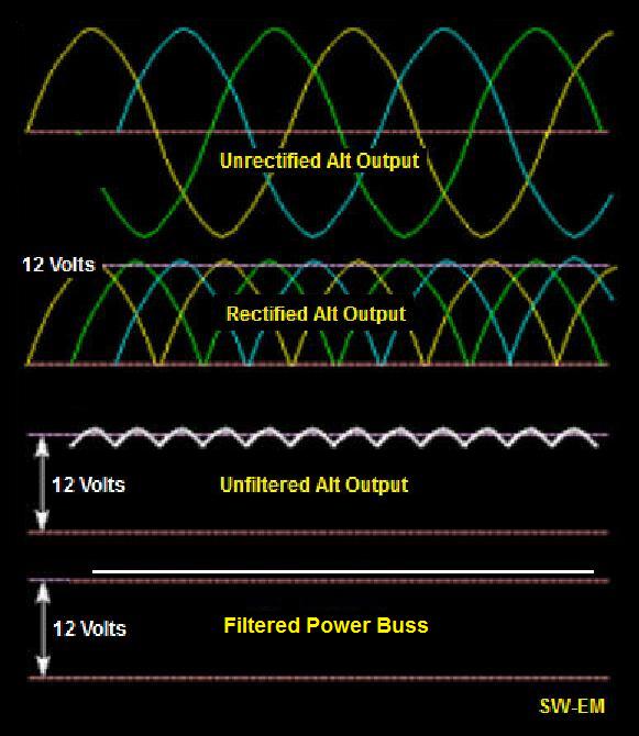
The observation? The digital voltage readout on the EFIS began cycling rapidly, almost as fast as the eye could see, in a range from roughly 13 to 16 volts. I say "roughly" because I have literally have no precise way to know how high it was spiking, or how low. It simply cycled too fast for the display to keep up.
With the avionics offline, only the GRT Sport was exposed to the cycling voltage. Didn't miss a beat, but I did not open its aux battery input, so I don't know if the primary power input voltage cycled low enough to cause a reboot.
It would also be nice to know how high the voltage is actually going. Anyone have a laptop with the necessary input to record a similar test at a high sample rate? I guess I could buy something, but nothing I already have handy will do it. The extension cord for my old o-scope is definitely not long enough")
I know it should work that way, but what really happens?
Sunday evening, a quick test, Plane Power 60A, 4500 feet over 08A. Open the avionics master (yes, I have one) to disconnect the radio, transponder, GPS, intercom, and autopilot...just a caution. Open the master switch. EFIS remains up, as it is connected to the main bus, which remained connected to the alternator. Both electronic ignitions remain up, as they have their own battery-direct feeds.
The observation? The digital voltage readout on the EFIS began cycling rapidly, almost as fast as the eye could see, in a range from roughly 13 to 16 volts. I say "roughly" because I have literally have no precise way to know how high it was spiking, or how low. It simply cycled too fast for the display to keep up.
With the avionics offline, only the GRT Sport was exposed to the cycling voltage. Didn't miss a beat, but I did not open its aux battery input, so I don't know if the primary power input voltage cycled low enough to cause a reboot.
It would also be nice to know how high the voltage is actually going. Anyone have a laptop with the necessary input to record a similar test at a high sample rate? I guess I could buy something, but nothing I already have handy will do it. The extension cord for my old o-scope is definitely not long enough
Last edited: