Please see my sketch. I am making my own two tube Pitot AOA. Variation on Van's design but two tubes, second for AOA. It will not use AN fitting but machined fitting. I don't want heated Pitot. I could go Dynon non heated and a mast, for under $400. This design is free and I hope will do the same thing, lighter. .
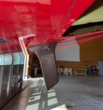
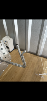
I tried to look up Cd (Drag Coefficient) for the two pitot tubes. I assume Cd of 0.40 for the aero shape mast version. And Cd 0.9-1.0 for the two 1/4" diameter tube. However that is harder to nail down, but I think pretty close.
What doe you think of the two tube design? Drag comparison?
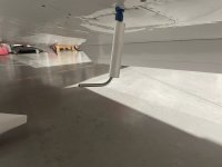
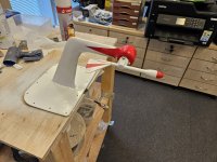
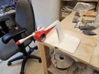
(My calculations est 0.5 lbs drag for either one, about the same? You have 3 times the Cd but 1/3rd of the area for the round tubes. . Seems to be pretty close. I have a machined fitting that holds the two alum tubes and will be coming out of the access cover (RV-7), supported off the main spar flange with a bracket. I love how it is coming out. It will look similar to picture I photoshopped below (but better):


I tried to look up Cd (Drag Coefficient) for the two pitot tubes. I assume Cd of 0.40 for the aero shape mast version. And Cd 0.9-1.0 for the two 1/4" diameter tube. However that is harder to nail down, but I think pretty close.
What doe you think of the two tube design? Drag comparison?
(My calculations est 0.5 lbs drag for either one, about the same? You have 3 times the Cd but 1/3rd of the area for the round tubes. . Seems to be pretty close. I have a machined fitting that holds the two alum tubes and will be coming out of the access cover (RV-7), supported off the main spar flange with a bracket. I love how it is coming out. It will look similar to picture I photoshopped below (but better):

 What? I know it is a folktale "Br'er Rabbit and the Briar Patch" by

")
") Believe the SCIENCE!!!! This is SWAG (Scientific Wild *** Guessing).
Believe the SCIENCE!!!! This is SWAG (Scientific Wild *** Guessing).


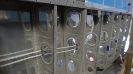
 It is off the shelf and needed if I go heated pitot. I'm set up to retrofit, even after bottom wing skin is nailed down, if I changed my mind..