Van's Air Force
You are using an out of date browser. It may not display this or other websites correctly.
You should upgrade or use an alternative browser.
You should upgrade or use an alternative browser.
AOA recommendations
- Thread starter rick57
- Start date

Standalone AoA’s are a tricky recomendation. We are finding that the optimum AoA instruments give you variable tones - increasing in “urgency” as you get closer to stall AoA. Unfortunately, not many standalones do this - most give you discrete tones at some arbitrary speed )flap speed is often used) and stall - not much different than a stall warning horn. The OnSpeed is superior in this regard - it gives variable tones, just liek in a fighter. Unfortunately, I am not sure that you can get/build one right now (calling Dr. Vac, Dr. Vac to the thread please!!) because of a shortage of obsolete processors, and they are still working to port the software and hardware to a new processor. Mike Vacaro, please correct me if I am wrong on this - I like flying with my OnSpeed!
The Alpha Systems are very good units, well made, accurate, but a little pricey.
Garmin is hard to beat - unfortunately, the G5 doesn’t support it, you’ll need some additional hardware.
Most folks get AoA free with their EFIS’s…one of the biggest challenges those of us working to promote AoA face is the shortage of good units for airplanes without an EFIS - just the problem the OP is looking at.
I have a G3X system but my AOA is from Advanced Flight Systems: https://angle-of-attack.com/aoa.htm
I've been pretty happy with this unit, but it is definitely an older design, probably 20 years or more. Apparently you can still get them from Spruce. If I was building or retrofitting an airplane today, I'd probably go with the Garmin system because integration is the hallmark of this panel. The AFS system is stand-alone, but I have to say it seems to work as advertised.
--Ron
I have a G3X system but my AOA is from Advanced Flight Systems: https://angle-of-attack.com/aoa.htm
I've been pretty happy with this unit, but it is definitely an older design, probably 20 years or more. Apparently you can still get them from Spruce. If I was building or retrofitting an airplane today, I'd probably go with the Garmin system because integration is the hallmark of this panel. The AFS system is stand-alone, but I have to say it seems to work as advertised.
--Ron
I have that AOA from Advanced Flight Systems also and very happy with it for over 20 years.
One of the first, simple, stand alone (no needed fancy glass), easy to calibrate, well made, and still works great after 20 years and over 1100 flights hours.
Last edited:
That’s a shame that the OnSpeed system is not currently available. I haven’t found the Dynon AoA on the Skyview to be as intuitive as the OnSpeed system appears to be from watching all of Vacs YouTube videos. Good luck to Vac finding a solution, I will be patiently waiting in line for an updated system that doesn’t require me to resurrect my previous life’s avionics tech.
I flew something like that for a few thousand hrs on a biz jet and it was excellent. Used it for approaches as well as max altitude ops.My rv9 had an older mechanical unit called a Lift Reserve indicator. No electrical required. It worked well, perhaps you can find a used one for sale.
Chris, please let me know your findings. Rick N443DTInstalling this system in my 4 ,Alpha AOA. Not flying yet so nothing to report.
Chris RV 4 N1212R
Will do..Chris, please let me know your findings. Rick N443DT
Fffflats
Well Known Member
Mine is theirs too; no electricity very simple but needs a light at night. It is a good pick though recommend rotating the gauge ninety degrees clockwise so high slow is up low fast is down.My rv9 had an older mechanical unit called a Lift Reserve indicator. No electrical required. It worked well, perhaps you can find a used one for sale.
Fffflats
Well Known Member
It’s available at Spruce: https://www.aircraftspruce.com/catalog/inpages/liftmonitor.phpMy rv9 had an older mechanical unit called a Lift Reserve indicator. No electrical required. It worked well, perhaps you can find a used one for sale.
and here is the gentleman who took it over from Lift Reserve: https://lift-mgt.com/
though he sounded older so don’t know if he’s still doing them.
Fffflats
Well Known Member
Mine is set such that two tics into the green is great for point landings and four tics for wheel landings. Stall is edge of red power off and maybe half way into the red power on while flap setting surprisingly has little impact. As it is a pressure differential system and not true AOA, high g stall occurs at a lower display, however. But still far better than ASI. Best glide is needle barely alive off the bottom of the rotated gauge.Mine is theirs too; no electricity very simple but needs a light at night. It is a good pick though recommend rotating the gauge ninety degrees clockwise so high slow is up low fast is down.
Fffflats
Well Known Member
Consider pairing that AOA with an inexpensive audio feedback radar altimeter such as those linked in the first paragraph of https://medium.com/@jamesmcclaranallen/improve-your-landings-with-aoa-power-techniques-04601584fb3a
While you’re there, see how much more AOA can do for you aside from energy safety margin awareness.
While you’re there, see how much more AOA can do for you aside from energy safety margin awareness.
Fffflats
Well Known Member
If on a jet, it was probably a true AOA off a true AOA vane as opposed to a pressure differential system.I flew something like that for a few thousand hrs on a biz jet and it was excellent. Used it for approaches as well as max altitude ops.
I had the original LRI on my first RV6 25 years ago and liked it, so I did the same thing again on my “new” RV6. The new LRI is the one mentioned above as the lift-mgt unit. It came with that clunky white plastic probe, which I didn’t like. A well known VAF’er had a metal one like the original LRI, and the same as used on the Alpha System AOA, which he generously traded me for. He took one look at the plastic one and tossed it in the trash. I mounted it “into” the top of my glareshield using a bracket I made, and attached (taped) a small LED light to the face of the instrument controlled by my IP dimmer. It just makes me smile when I fly at night. That tiny light is the only thing that requires electricity, and I seldom fly at night. It is about as simple as you can get.It’s available at Spruce: https://www.aircraftspruce.com/catalog/inpages/liftmonitor.php
and here is the gentleman who took it over from Lift Reserve: https://lift-mgt.com/
though he sounded older so don’t know if he’s still doing them.
I also have the AOA option in my GRT Horizon. It’s totally separate from the LRI, but uses the same angled pressure port from the LRI probe - tee’d off behind the panel feeding the AOA port on the GRT. These two systems were flight tested/programmed separately. With the GRT system I get chevrons and an AOA feather on my PFD, and I also get an oral warning with increasing intensity as I approach my critical AOA. On final approach I seldom look at my PFD, but the oral warning comes in very handy. My focus is forward looking through the AOA gage on the glareshield, allowing me get get slow enough to make an easy three point landing.
Attachments
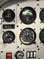
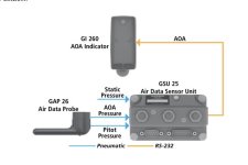
This data is from a previous post in June of 2023 when I was looking for an AOA solution. I ended up replacing my heated pitot tube with the Dynon heated pitot/AOA probe. Since I have an AFS EFIS it already has AOA available so I just had to run an extra AOA line back to the existing Adhars and mounted the heater control unit near the probe inside the wing.What AOA instrument or system would you recommend? Simple is better, only electronic device I have is Garmin G5 with GPS and magnetometer. Thanks in advance. Rick
In your case a Garmin GAP-26 heated AOA system may offer you an easier acceptable solution. Even though Aircraft Spruce says that this cannot be used as a stand alone system this is incorrect according to Garmin. I contacted them directly and they stated that it can be installed and used as a separate AOA system with the GI-260 externally mounted display. According to my e-mails with Garmin, the calibration does not have to be done on the G3X, it can be done directly on the GI-260 display using the Test button. G3Expert can chime in here but all the online data indicates that you have to have the G3X but evidently that is not true.
I was going to buy this system because I would have liked having the external display mounted on the glare shield instead of buried in the EFIS. I don’t look at the EFIS in the flare anyway, I just listen for the tones. Having your AOA display up high in your field of vision would be a plus I think.
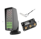
Aircraft Spruce has the heated version and you can get it from Garmin as well.

Garmin AOA System Indicator 14V / 28V - Heated | Aircraft Spruce ®
Garmin AOA System Indicator 14V / 28V - Heated Provides AOA with a single glance during critical flight phases. Intuitive display provides both visual and audible indications of AOA. Normalized AOA provides superior performance in all fligh


At $1945 it isn’t cheap for the heated version but this is all you need and should be a fairly easy install. Take a look at the manual located here:
Attachments

Last edited:

Fffflats
Well Known Member
Is it the same angle or similar idea angle? If your angle is twice your critical angle, then your accelerated stall concerns for sake of being a pressure differential as opposed to true AOA vane go away.I had the original LRI on my first RV6 25 years ago and liked it, so I did the same thing again on my “new” RV6. The new LRI is the one mentioned above as the lift-mgt unit. It came with that clunky white plastic probe, which I didn’t like. A well known VAF’er had a metal one like the original LRI, and the same as used on the Alpha System AOA, which he generously traded me for. He took one look at the plastic one and tossed it in the trash. I mounted it “into” the top of my glareshield using a bracket I made, and attached (taped) a small LED light to the face of the instrument controlled by my IP dimmer. It just makes me smile when I fly at night. That tiny light is the only thing that requires electricity, and I seldom fly at night. It is about as simple as you can get.
I also have the AOA option in my GRT Horizon. It’s totally separate from the LRI, but uses the same angled pressure port from the LRI probe - tee’d off behind the panel feeding the AOA port on the GRT. These two systems were flight tested/programmed separately. With the GRT system I get chevrons and an AOA feather on my PFD, and I also get an oral warning with increasing intensity as I approach my critical AOA. On final approach I seldom look at my PFD, but the oral warning comes in very handy. My focus is forward looking through the AOA gage on the glareshield, allowing me get get slow enough to make an easy three point landing.
I think the LRI gage is a similar/same angle idea, but not sure. Gives me something to do/test. I also think the GRT AOA indication is different because I get the aural warning on the bottom of a loop on a 3g pull out and my airspeed wings level is still well above my normal 1g unaccelerated stall speed. I don’t think I’ve actually looked at my LRI indicator during that phase - but I will…
Fffflats
Well Known Member
Forgive me for copy paste from elsewhere though it hits my point RE pressure differential vs true AOA. Note I’ll say Lift Reserve but really this more broadly applies to all pressure differential systems. First, a reference to Jim Covington of the Titan Group via Stoney Lake https://www.stoneylake.org/pipcom/AOAr.htm for several quotes:I think the LRI gage is a similar/same angle idea, but not sure. Gives me something to do/test. I also think the GRT AOA indication is different because I get the aural warning on the bottom of a loop on a 3g pull out and my airspeed wings level is still well above my normal 1g unaccelerated stall speed. I don’t think I’ve actually looked at my LRI indicator during that phase - but I will…
“This instrument measures the difference in dynamic pressure at two ports. The pressure at each port is proportional to two things - the dynamic pressure due to airspeed, as would be measured by a perfect pitot tube, and the cosine of the angle of the axis of port opening relative to the angle of the oncoming air - the angle of attack of that particular port. As the angle of attack of the instrument changes, the difference between the dynamic pressures at the two ports also changes. As you increase the angle of attack, the angle of attack of the top port increases and the bottom one decreases, so the pressure at the top one decreases and the bottom one increases, so our instrument shows a change in the difference between the two. So far, so good - it's pretty close to an angle of attack instrument.
“Here's where the problem is - changing the angle of attack is not the only way to change the difference in pressure between the two ports. You can also change this by changing the airspeed without changing the angle of attack. Imagine the top port is directly into the wind, and the bottom port is angled downward about 45 degrees. The pressure at the top port will be 100% of the dynamic pressure, and the pressure at the bottom port will be about 70% of the dynamic pressure. Our instrument shows us some reading (I don't know what reading - it depends on how it's calibrated.)
“Now imagine you double the airspeed in the wind tunnel. The dynamic pressure with go up by a factor of 4. Here's the important point: *The difference in pressure between the two points will also go up by a factor of 4. * So the differential pressure gauge changes! This is why one of the major manufacturers of a similar system calls it a ‘Lift Reserve Indicator.’ It shows the ‘lift’ your wing is producing, not the angle of attack. Now if you're not turning hard tight turns, this really doesn't matter all that much. You do want to know how much lift you're making, especially during landing and when trying to maintain Vx, Vy or best glide.
Hence why your gauge doesn’t quite display critical angle for stall and reads a touch lower in the accelerated stall. This is, however, far better than ASI’s accelerated stall deviations in reading from stall, and in the case of a pressure differential gauge, it can be eliminated with ports spaced by an angle equal to twice your critical angle. As manufacturers don’t know your specific critical angle, they’ll build close enough with partial reduction in error. Which brings me to my copy paste thoughts from an old email thread:
(I would challenge Vx and Vy as they’re not strictly based on the aero, they’ve got to account for propulsion too; you can approximate them only slightly better with AOA as you can speed. AOAx and AOAy resolve weight but both sets Vx, Vy, AOAx, and AOAy fail to account for density altitude to include but not limited to if/when compressibility becomes factor. But this gets complicated really quickly and is a topic for another time. If you want to ponder it, start by considering how you find absolute ceiling (you can neglect compressibility for this pondering). Now consider the implications of this in terms of what is constant and what varies. A jet has constant AOAx till compressibility comes a factor while AOAy sweeps up with altitude to meet AOAx at max ceiling. A theoretical prop would have constant AOAy with AOAx sweeping down with altitude till both met at ceiling and this AOAy would happen at min power required, but due to propeller inefficiencies, AOAy starts much lower than min power and sweeps up while AOAx starts a bit higher than min power sweeping down with altitude (see Aerodynamics for Naval Aviators).)
So, if we’re at 100 and we assume 100 produces a sufficiently low AOA so as to be negligible to front port angle, the bottom (slant) port reads a 70 giving us a ratio of 1.43 but a differential of 30 while if we were at 400 at the same angle of attack, the slant port would see 280 with the same ratio 1.43 but a differential of 120. This is why the accelerated stall shifted on the Lift Reserve as it only approximates an AOA. A true AOA vane shows no shift.
In our case, we stalled power off straight ahead at around 60 mph and “AOA” at the edge of the red and white. In the accelerated, we started at 150-ish, rolled, and pulled, and saw the stall in the middle of the white. We had some other differences in there as power off / power on makes a difference. Believe I had my placard marked as Full Flap and Half Flap versus No Flap on gauge stall locations, but turns out this has much less effect on the gauge than does power on versus power off in my airplane such that I’ve made a new placard marking power off versus power on and discounting flap position. Power on unaccelerated is halfway into the red or 1.5 ticks into the red. Hence, as we likely stayed power on in the accelerated stall, we saw roughly a three tick shift of our stall on our “AOA” unaccelerated to highly accelerated.
Back to Jim Covington for a moment:
“So to sum up - it's a great instrument. If you don't have one, consider getting it. It's well worth the investment. Your landings will be smoother and shorter, guaranteed. But don't count on it to tell you when you're about to stall in a 5-G pull-up from a split S. For that you need a real AoA instrument with a display readout near the center of your field of vision.
And from my email copy paste:
Let’s take this one on.
Let’s just start by saying you shouldn’t be doing 5g in a Split S as you shouldn’t have adequate speed to pull 5g as you should slow before starting the Split S. Fighters have an exception here as they may start sufficiently fast though if they do so, it is because they either want energy to go up after the Split S or have energy to fight a rate war after the Split S (two different ideas, two different game plans, not two ways of explaining an idea). If in a radius fight (a third game plan), they too would want to be slow going into a Split S.
Our roll into a steep AOB and pull, however, was close to this 5g stall scenario.
Lift = 1/2 Clmax p Vs^2 A
5 Lift = 1/2 Clmax p Vaccel^2 A
Lift = 1/10 Clmax p Vaccel^2 A
Vs^2 = 1/5 Vaccel^2
√1/5 = Vs/Vaccel
Vaccel = Vs/.447
Vaccel = 2.2 Vs
While the critical angle of attack is constant, and this speed ratio for 1 g unaccelerated stall to 5 g accelerated stall is constant at 2.2, the speeds themselves change significantly, but what of the pressures at the ports? They change too but at a much dampened value.
For ease of comparison, rather than converting to pressures, I’ll look at speed of air at each port in each condition.
My probe has a front port at zero degrees and a bottom probe at 45 degrees down. Stalls typically occur for most airplanes at fifteen to twenty degrees AOA.
If we presume a critical angle of fifteen degrees, the front port will be fifteen degrees above relative wind while the bottom port will be thirty degrees below. We’ll assume an unaccelerated stall speed of 65 mph which would be for an overweight RV. We’re going a little fast as the faster the worse the skewed effects.
Front probe 65 cos (15) = 63
Bottom probe 65 cos (30) = 56
For a difference of seven
At 5g, we have 65 √5 = 145
FP 145 cos (15) = 140
BP 145 cos (30) = 126
For a difference of fourteen
And the difference of differences is seven. So the speed difference is eighty while the differences in the probe port comparisons is only seven. Much closer to zero or holding constant. But not perfect as a vane would be. Yet significantly more functional than speed in terms of stall avoidance. Seems you actually can use the Lift Reserve at 5g though if you’re going to do so regularly, you may want to make a 5g reference mark. If not regularly doing so, avoid the caution range using it as margin. (The FIKI Cirrus is ok; it is a vane not a lift reserve. Icon A5? Probably not pulling 5g.) (Do look up the Icon POH and see how often and in what ways they use AOA in normal and emergency procedures!)
If we presume a critical angle of twenty degrees, the front port will be twenty degrees above the relative wind and the bottom port will be twenty-five degrees below.
FP 65 cos (20) = 61
BP 65 cos (25) = 59
For a difference of two
At 5g,
FP 145 cos (20) = 136
BP 145 cos (25) = 131
For a difference of five
And the difference of differences is three. Again, the airspeed is seeing a difference of eighty. The ports, however, would only shift a pressure difference correlating to three mph whereas we want zero to reflect no shift.
Lift Reserve not perfect but not bad. Stay in the green for high g maneuvering and we’re ok.
The slower your unaccelerated stall speed is the less these differences will be and the closer your critical angle stall angle of attack is to half the angular difference between the front port and bottom port the less these differences will be.
Now consider the 2g case as that is likely the extreme for general aviation outside of aerobatic aircraft.
Vs1 = √2 Vs = 1.4 Vs
Critical angle 15
FP 92 cos (15) = 89
BP 92 cos (30) = 80
for a difference of differences of two.
Critical angle 20
FP 92 cos (20) = 86
BP 92 cos (25) = 83
for a difference of differences of one.
Anyway, for any airplane that stalls less than 100 and isn’t typically going to pull more than 4g, the pressure differential Lift Reserve not only is much better approximation for AOA than anything other than AOA itself, it is close enough that the differences should be considered negligible. Such could also be mitigated by seeking port angles at twice stall angle. Or, as most of us don’t get a choice on probe shape, to adjust the probe such that mid-port angle coincides with stall angle (but this also shifts where stall occurs on the gauge, so you may not want to in the tradeoff). Other Lift Reserve systems use a combined pitot-tube “AOA” probe, so shifting the probe angle also isn’t an option for them.
Even for the higher g aerobatic, it is significantly better than is airspeed and is workable as you can stay out of the caution range at high speed while you’ll bleed the speed pretty quickly thus getting into much more accurate pressure comparison lift reserve in lieu of when you’d want it. After all, at the high end, you’re concerned with speed and g so as not to overstress while you transition to AOA as you transition to the low end of energy. The discrepancies with the pressure comparison occur in an area you generally don’t care about AOA. They occur in a consistent manner such that if you really wanted to, you could create applicable reference marks.
Remember the other error source: Lift Reserves are susceptible to both vertical and horizontal gusts while speed is only susceptible to horizontal (relative to airframe) and true AOA is only susceptible to vertical (relative to airframe). This one actually has concern while both true AOA and Lift Reserve more readily highlight the gusts which impact them due to the nonlinearity between AOA and airspeed. Selection of range scale can amplify the noticeability of the gusts. This is the real concern for Lift Reserve.
I would be remiss if I also didn’t copy this paragraph though noting time was really a couple years ago not the other night:
And mine is not illuminated so unavailable at night. This really sucks when you go for night currency after having gotten used to it. Made for an uncomfortable experience the other night.
Edhunter,My rv9 had an older mechanical unit called a Lift Reserve indicator. No electrical required. It worked well, perhaps you can find a used one for sale.
I also had the Lift system. It was solely based on differential air flow input.
Once calibrated to my plane it was amazing.
not dependent on electrics either.
Simple to install too.
My short field distance landings were improved once I flew the AOA vs. my prior efforts.
Daddyman58
Fffflats
Well Known Member
Another way to think of it is if the difference between pressures at stall is zero, doesn’t matter if both are 65, 145, or 400. Twice stall angle for port angle makes for zeroized difference between the ports at stall as they’ll have equal ram components at stall. This is why the Dynon, and I would assume Garmin, dual pitot-AOA is at 36 degrees between ports. 18 is very likely near your critical angle.Forgive me for copy paste from elsewhere though it hits my point RE pressure differential vs true AOA. Note I’ll say Lift Reserve but really this more broadly applies to all pressure differential systems. First, a reference to Jim Covington of the Titan Group via Stoney Lake https://www.stoneylake.org/pipcom/AOAr.htm for several quotes:
“This instrument measures the difference in dynamic pressure at two ports. The pressure at each port is proportional to two things - the dynamic pressure due to airspeed, as would be measured by a perfect pitot tube, and the cosine of the angle of the axis of port opening relative to the angle of the oncoming air - the angle of attack of that particular port. As the angle of attack of the instrument changes, the difference between the dynamic pressures at the two ports also changes. As you increase the angle of attack, the angle of attack of the top port increases and the bottom one decreases, so the pressure at the top one decreases and the bottom one increases, so our instrument shows a change in the difference between the two. So far, so good - it's pretty close to an angle of attack instrument.
“Here's where the problem is - changing the angle of attack is not the only way to change the difference in pressure between the two ports. You can also change this by changing the airspeed without changing the angle of attack. Imagine the top port is directly into the wind, and the bottom port is angled downward about 45 degrees. The pressure at the top port will be 100% of the dynamic pressure, and the pressure at the bottom port will be about 70% of the dynamic pressure. Our instrument shows us some reading (I don't know what reading - it depends on how it's calibrated.)
“Now imagine you double the airspeed in the wind tunnel. The dynamic pressure with go up by a factor of 4. Here's the important point: *The difference in pressure between the two points will also go up by a factor of 4. * So the differential pressure gauge changes! This is why one of the major manufacturers of a similar system calls it a ‘Lift Reserve Indicator.’ It shows the ‘lift’ your wing is producing, not the angle of attack. Now if you're not turning hard tight turns, this really doesn't matter all that much. You do want to know how much lift you're making, especially during landing and when trying to maintain Vx, Vy or best glide.
Hence why your gauge doesn’t quite display critical angle for stall and reads a touch lower in the accelerated stall. This is, however, far better than ASI’s accelerated stall deviations in reading from stall, and in the case of a pressure differential gauge, it can be eliminated with ports spaced by an angle equal to twice your critical angle. As manufacturers don’t know your specific critical angle, they’ll build close enough with partial reduction in error. Which brings me to my copy paste thoughts from an old email thread:
(I would challenge Vx and Vy as they’re not strictly based on the aero, they’ve got to account for propulsion too; you can approximate them only slightly better with AOA as you can speed. AOAx and AOAy resolve weight but both sets Vx, Vy, AOAx, and AOAy fail to account for density altitude to include but not limited to if/when compressibility becomes factor. But this gets complicated really quickly and is a topic for another time. If you want to ponder it, start by considering how you find absolute ceiling (you can neglect compressibility for this pondering). Now consider the implications of this in terms of what is constant and what varies. A jet has constant AOAx till compressibility comes a factor while AOAy sweeps up with altitude to meet AOAx at max ceiling. A theoretical prop would have constant AOAy with AOAx sweeping down with altitude till both met at ceiling and this AOAy would happen at min power required, but due to propeller inefficiencies, AOAy starts much lower than min power and sweeps up while AOAx starts a bit higher than min power sweeping down with altitude (see Aerodynamics for Naval Aviators).)
So, if we’re at 100 and we assume 100 produces a sufficiently low AOA so as to be negligible to front port angle, the bottom (slant) port reads a 70 giving us a ratio of 1.43 but a differential of 30 while if we were at 400 at the same angle of attack, the slant port would see 280 with the same ratio 1.43 but a differential of 120. This is why the accelerated stall shifted on the Lift Reserve as it only approximates an AOA. A true AOA vane shows no shift.
In our case, we stalled power off straight ahead at around 60 mph and “AOA” at the edge of the red and white. In the accelerated, we started at 150-ish, rolled, and pulled, and saw the stall in the middle of the white. We had some other differences in there as power off / power on makes a difference. Believe I had my placard marked as Full Flap and Half Flap versus No Flap on gauge stall locations, but turns out this has much less effect on the gauge than does power on versus power off in my airplane such that I’ve made a new placard marking power off versus power on and discounting flap position. Power on unaccelerated is halfway into the red or 1.5 ticks into the red. Hence, as we likely stayed power on in the accelerated stall, we saw roughly a three tick shift of our stall on our “AOA” unaccelerated to highly accelerated.
Back to Jim Covington for a moment:
“So to sum up - it's a great instrument. If you don't have one, consider getting it. It's well worth the investment. Your landings will be smoother and shorter, guaranteed. But don't count on it to tell you when you're about to stall in a 5-G pull-up from a split S. For that you need a real AoA instrument with a display readout near the center of your field of vision.
And from my email copy paste:
Let’s take this one on.
Let’s just start by saying you shouldn’t be doing 5g in a Split S as you shouldn’t have adequate speed to pull 5g as you should slow before starting the Split S. Fighters have an exception here as they may start sufficiently fast though if they do so, it is because they either want energy to go up after the Split S or have energy to fight a rate war after the Split S (two different ideas, two different game plans, not two ways of explaining an idea). If in a radius fight (a third game plan), they too would want to be slow going into a Split S.
Our roll into a steep AOB and pull, however, was close to this 5g stall scenario.
Lift = 1/2 Clmax p Vs^2 A
5 Lift = 1/2 Clmax p Vaccel^2 A
Lift = 1/10 Clmax p Vaccel^2 A
Vs^2 = 1/5 Vaccel^2
√1/5 = Vs/Vaccel
Vaccel = Vs/.447
Vaccel = 2.2 Vs
While the critical angle of attack is constant, and this speed ratio for 1 g unaccelerated stall to 5 g accelerated stall is constant at 2.2, the speeds themselves change significantly, but what of the pressures at the ports? They change too but at a much dampened value.
For ease of comparison, rather than converting to pressures, I’ll look at speed of air at each port in each condition.
My probe has a front port at zero degrees and a bottom probe at 45 degrees down. Stalls typically occur for most airplanes at fifteen to twenty degrees AOA.
If we presume a critical angle of fifteen degrees, the front port will be fifteen degrees above relative wind while the bottom port will be thirty degrees below. We’ll assume an unaccelerated stall speed of 65 mph which would be for an overweight RV. We’re going a little fast as the faster the worse the skewed effects.
Front probe 65 cos (15) = 63
Bottom probe 65 cos (30) = 56
For a difference of seven
At 5g, we have 65 √5 = 145
FP 145 cos (15) = 140
BP 145 cos (30) = 126
For a difference of fourteen
And the difference of differences is seven. So the speed difference is eighty while the differences in the probe port comparisons is only seven. Much closer to zero or holding constant. But not perfect as a vane would be. Yet significantly more functional than speed in terms of stall avoidance. Seems you actually can use the Lift Reserve at 5g though if you’re going to do so regularly, you may want to make a 5g reference mark. If not regularly doing so, avoid the caution range using it as margin. (The FIKI Cirrus is ok; it is a vane not a lift reserve. Icon A5? Probably not pulling 5g.) (Do look up the Icon POH and see how often and in what ways they use AOA in normal and emergency procedures!)
If we presume a critical angle of twenty degrees, the front port will be twenty degrees above the relative wind and the bottom port will be twenty-five degrees below.
FP 65 cos (20) = 61
BP 65 cos (25) = 59
For a difference of two
At 5g,
FP 145 cos (20) = 136
BP 145 cos (25) = 131
For a difference of five
And the difference of differences is three. Again, the airspeed is seeing a difference of eighty. The ports, however, would only shift a pressure difference correlating to three mph whereas we want zero to reflect no shift.
Lift Reserve not perfect but not bad. Stay in the green for high g maneuvering and we’re ok.
The slower your unaccelerated stall speed is the less these differences will be and the closer your critical angle stall angle of attack is to half the angular difference between the front port and bottom port the less these differences will be.
Now consider the 2g case as that is likely the extreme for general aviation outside of aerobatic aircraft.
Vs1 = √2 Vs = 1.4 Vs
Critical angle 15
FP 92 cos (15) = 89
BP 92 cos (30) = 80
for a difference of differences of two.
Critical angle 20
FP 92 cos (20) = 86
BP 92 cos (25) = 83
for a difference of differences of one.
Anyway, for any airplane that stalls less than 100 and isn’t typically going to pull more than 4g, the pressure differential Lift Reserve not only is much better approximation for AOA than anything other than AOA itself, it is close enough that the differences should be considered negligible. Such could also be mitigated by seeking port angles at twice stall angle. Or, as most of us don’t get a choice on probe shape, to adjust the probe such that mid-port angle coincides with stall angle (but this also shifts where stall occurs on the gauge, so you may not want to in the tradeoff). Other Lift Reserve systems use a combined pitot-tube “AOA” probe, so shifting the probe angle also isn’t an option for them.
Even for the higher g aerobatic, it is significantly better than is airspeed and is workable as you can stay out of the caution range at high speed while you’ll bleed the speed pretty quickly thus getting into much more accurate pressure comparison lift reserve in lieu of when you’d want it. After all, at the high end, you’re concerned with speed and g so as not to overstress while you transition to AOA as you transition to the low end of energy. The discrepancies with the pressure comparison occur in an area you generally don’t care about AOA. They occur in a consistent manner such that if you really wanted to, you could create applicable reference marks.
Remember the other error source: Lift Reserves are susceptible to both vertical and horizontal gusts while speed is only susceptible to horizontal (relative to airframe) and true AOA is only susceptible to vertical (relative to airframe). This one actually has concern while both true AOA and Lift Reserve more readily highlight the gusts which impact them due to the nonlinearity between AOA and airspeed. Selection of range scale can amplify the noticeability of the gusts. This is the real concern for Lift Reserve.
I would be remiss if I also didn’t copy this paragraph though noting time was really a couple years ago not the other night:
And mine is not illuminated so unavailable at night. This really sucks when you go for night currency after having gotten used to it. Made for an uncomfortable experience the other night.
Fffflats
Well Known Member
Which fighters have progressive tones? I know of none. Which have tones useful in landing? Again, I’m aware of none. The Hornets have tones at half and full flaps AOA limits while the legacy Hornet has a flaps up tone ivo old flight computer logic ‘stall’ region, though this is of more use to one circle fighting than anything else. The flaps half or full are really for asymmetric thrust concerns not stall concerns. These are binary, there or not tones. The tones are useless to landing a Hornet though the Indexer next to the HUD giving a peripheral color coded seeing, and the E bracket in field of view while checking lineup make for excellent AOA references. Note their Indexer is ‘stop light’ color coded not danger-safe coloring as civilian systems. See green you need to go faster, red need to slow, amber is good.Standalone AoA’s are a tricky recomendation. We are finding that the optimum AoA instruments give you variable tones - increasing in “urgency” as you get closer to stall AoA. Unfortunately, not many standalones do this - most give you discrete tones at some arbitrary speed )flap speed is often used) and stall - not much different than a stall warning horn. The OnSpeed is superior in this regard - it gives variable tones, just liek in a fighter. Unfortunately, I am not sure that you can get/build one right now (calling Dr. Vac, Dr. Vac to the thread please!!) because of a shortage of obsolete processors, and they are still working to port the software and hardware to a new processor. Mike Vacaro, please correct me if I am wrong on this - I like flying with my OnSpeed!
The Alpha Systems are very good units, well made, accurate, but a little pricey.
Garmin is hard to beat - unfortunately, the G5 doesn’t support it, you’ll need some additional hardware.
Most folks get AoA free with their EFIS’s…one of the biggest challenges those of us working to promote AoA face is the shortage of good units for airplanes without an EFIS - just the problem the OP is looking at.
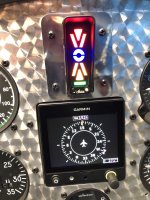
I personally love my stand alone for its simplicity. No power required. Little that can go wrong. Only thing, as mentioned before, rotated the gauge ninety clockwise so slow high is up and low fast is down. It is the Lift Reserve previously mentioned and linked. Gauge placed prominently similar to Icon A5. Tones are a nice feature. Especially progressive tones that include on-speed in their range. But simplicity and simplicity increased robustness is also nice.
Note if you fly like the Navy, you’ll only pull back on the stick for round out and flare keeping trimmed AOA value throughout your landing pattern (as mentioned in previously linked AOA and Power Techniques article). Fly this way and you cannot approach turn stall. For those teaching and pressing AOA in general aviation, very few actually fully teach and espouse AOA.
Fffflats,Forgive me for copy paste from elsewhere though it hits my point RE pressure differential vs true AOA. Note I’ll say Lift Reserve but really this more broadly applies to all pressure differential systems. First, a reference to Jim Covington of the Titan Group via Stoney Lake https://www.stoneylake.org/pipcom/AOAr.htm for several quotes:
“This instrument measures the difference in dynamic pressure at two ports. The pressure at each port is proportional to two things - the dynamic pressure due to airspeed, as would be measured by a perfect pitot tube, and the cosine of the angle of the axis of port opening relative to the angle of the oncoming air - the angle of attack of that particular port. As the angle of attack of the instrument changes, the difference between the dynamic pressures at the two ports also changes. As you increase the angle of attack, the angle of attack of the top port increases and the bottom one decreases, so the pressure at the top one decreases and the bottom one increases, so our instrument shows a change in the difference between the two. So far, so good - it's pretty close to an angle of attack instrument.
“Here's where the problem is - changing the angle of attack is not the only way to change the difference in pressure between the two ports. You can also change this by changing the airspeed without changing the angle of attack. Imagine the top port is directly into the wind, and the bottom port is angled downward about 45 degrees. The pressure at the top port will be 100% of the dynamic pressure, and the pressure at the bottom port will be about 70% of the dynamic pressure. Our instrument shows us some reading (I don't know what reading - it depends on how it's calibrated.)
“Now imagine you double the airspeed in the wind tunnel. The dynamic pressure with go up by a factor of 4. Here's the important point: *The difference in pressure between the two points will also go up by a factor of 4. * So the differential pressure gauge changes! This is why one of the major manufacturers of a similar system calls it a ‘Lift Reserve Indicator.’ It shows the ‘lift’ your wing is producing, not the angle of attack. Now if you're not turning hard tight turns, this really doesn't matter all that much. You do want to know how much lift you're making, especially during landing and when trying to maintain Vx, Vy or best glide.
Hence why your gauge doesn’t quite display critical angle for stall and reads a touch lower in the accelerated stall. This is, however, far better than ASI’s accelerated stall deviations in reading from stall, and in the case of a pressure differential gauge, it can be eliminated with ports spaced by an angle equal to twice your critical angle. As manufacturers don’t know your specific critical angle, they’ll build close enough with partial reduction in error. Which brings me to my copy paste thoughts from an old email thread:
(I would challenge Vx and Vy as they’re not strictly based on the aero, they’ve got to account for propulsion too; you can approximate them only slightly better with AOA as you can speed. AOAx and AOAy resolve weight but both sets Vx, Vy, AOAx, and AOAy fail to account for density altitude to include but not limited to if/when compressibility becomes factor. But this gets complicated really quickly and is a topic for another time. If you want to ponder it, start by considering how you find absolute ceiling (you can neglect compressibility for this pondering). Now consider the implications of this in terms of what is constant and what varies. A jet has constant AOAx till compressibility comes a factor while AOAy sweeps up with altitude to meet AOAx at max ceiling. A theoretical prop would have constant AOAy with AOAx sweeping down with altitude till both met at ceiling and this AOAy would happen at min power required, but due to propeller inefficiencies, AOAy starts much lower than min power and sweeps up while AOAx starts a bit higher than min power sweeping down with altitude (see Aerodynamics for Naval Aviators).)
So, if we’re at 100 and we assume 100 produces a sufficiently low AOA so as to be negligible to front port angle, the bottom (slant) port reads a 70 giving us a ratio of 1.43 but a differential of 30 while if we were at 400 at the same angle of attack, the slant port would see 280 with the same ratio 1.43 but a differential of 120. This is why the accelerated stall shifted on the Lift Reserve as it only approximates an AOA. A true AOA vane shows no shift.
In our case, we stalled power off straight ahead at around 60 mph and “AOA” at the edge of the red and white. In the accelerated, we started at 150-ish, rolled, and pulled, and saw the stall in the middle of the white. We had some other differences in there as power off / power on makes a difference. Believe I had my placard marked as Full Flap and Half Flap versus No Flap on gauge stall locations, but turns out this has much less effect on the gauge than does power on versus power off in my airplane such that I’ve made a new placard marking power off versus power on and discounting flap position. Power on unaccelerated is halfway into the red or 1.5 ticks into the red. Hence, as we likely stayed power on in the accelerated stall, we saw roughly a three tick shift of our stall on our “AOA” unaccelerated to highly accelerated.
Back to Jim Covington for a moment:
“So to sum up - it's a great instrument. If you don't have one, consider getting it. It's well worth the investment. Your landings will be smoother and shorter, guaranteed. But don't count on it to tell you when you're about to stall in a 5-G pull-up from a split S. For that you need a real AoA instrument with a display readout near the center of your field of vision.
And from my email copy paste:
Let’s take this one on.
Let’s just start by saying you shouldn’t be doing 5g in a Split S as you shouldn’t have adequate speed to pull 5g as you should slow before starting the Split S. Fighters have an exception here as they may start sufficiently fast though if they do so, it is because they either want energy to go up after the Split S or have energy to fight a rate war after the Split S (two different ideas, two different game plans, not two ways of explaining an idea). If in a radius fight (a third game plan), they too would want to be slow going into a Split S.
Our roll into a steep AOB and pull, however, was close to this 5g stall scenario.
Lift = 1/2 Clmax p Vs^2 A
5 Lift = 1/2 Clmax p Vaccel^2 A
Lift = 1/10 Clmax p Vaccel^2 A
Vs^2 = 1/5 Vaccel^2
√1/5 = Vs/Vaccel
Vaccel = Vs/.447
Vaccel = 2.2 Vs
While the critical angle of attack is constant, and this speed ratio for 1 g unaccelerated stall to 5 g accelerated stall is constant at 2.2, the speeds themselves change significantly, but what of the pressures at the ports? They change too but at a much dampened value.
For ease of comparison, rather than converting to pressures, I’ll look at speed of air at each port in each condition.
My probe has a front port at zero degrees and a bottom probe at 45 degrees down. Stalls typically occur for most airplanes at fifteen to twenty degrees AOA.
If we presume a critical angle of fifteen degrees, the front port will be fifteen degrees above relative wind while the bottom port will be thirty degrees below. We’ll assume an unaccelerated stall speed of 65 mph which would be for an overweight RV. We’re going a little fast as the faster the worse the skewed effects.
Front probe 65 cos (15) = 63
Bottom probe 65 cos (30) = 56
For a difference of seven
At 5g, we have 65 √5 = 145
FP 145 cos (15) = 140
BP 145 cos (30) = 126
For a difference of fourteen
And the difference of differences is seven. So the speed difference is eighty while the differences in the probe port comparisons is only seven. Much closer to zero or holding constant. But not perfect as a vane would be. Yet significantly more functional than speed in terms of stall avoidance. Seems you actually can use the Lift Reserve at 5g though if you’re going to do so regularly, you may want to make a 5g reference mark. If not regularly doing so, avoid the caution range using it as margin. (The FIKI Cirrus is ok; it is a vane not a lift reserve. Icon A5? Probably not pulling 5g.) (Do look up the Icon POH and see how often and in what ways they use AOA in normal and emergency procedures!)
If we presume a critical angle of twenty degrees, the front port will be twenty degrees above the relative wind and the bottom port will be twenty-five degrees below.
FP 65 cos (20) = 61
BP 65 cos (25) = 59
For a difference of two
At 5g,
FP 145 cos (20) = 136
BP 145 cos (25) = 131
For a difference of five
And the difference of differences is three. Again, the airspeed is seeing a difference of eighty. The ports, however, would only shift a pressure difference correlating to three mph whereas we want zero to reflect no shift.
Lift Reserve not perfect but not bad. Stay in the green for high g maneuvering and we’re ok.
The slower your unaccelerated stall speed is the less these differences will be and the closer your critical angle stall angle of attack is to half the angular difference between the front port and bottom port the less these differences will be.
Now consider the 2g case as that is likely the extreme for general aviation outside of aerobatic aircraft.
Vs1 = √2 Vs = 1.4 Vs
Critical angle 15
FP 92 cos (15) = 89
BP 92 cos (30) = 80
for a difference of differences of two.
Critical angle 20
FP 92 cos (20) = 86
BP 92 cos (25) = 83
for a difference of differences of one.
Anyway, for any airplane that stalls less than 100 and isn’t typically going to pull more than 4g, the pressure differential Lift Reserve not only is much better approximation for AOA than anything other than AOA itself, it is close enough that the differences should be considered negligible. Such could also be mitigated by seeking port angles at twice stall angle. Or, as most of us don’t get a choice on probe shape, to adjust the probe such that mid-port angle coincides with stall angle (but this also shifts where stall occurs on the gauge, so you may not want to in the tradeoff). Other Lift Reserve systems use a combined pitot-tube “AOA” probe, so shifting the probe angle also isn’t an option for them.
Even for the higher g aerobatic, it is significantly better than is airspeed and is workable as you can stay out of the caution range at high speed while you’ll bleed the speed pretty quickly thus getting into much more accurate pressure comparison lift reserve in lieu of when you’d want it. After all, at the high end, you’re concerned with speed and g so as not to overstress while you transition to AOA as you transition to the low end of energy. The discrepancies with the pressure comparison occur in an area you generally don’t care about AOA. They occur in a consistent manner such that if you really wanted to, you could create applicable reference marks.
Remember the other error source: Lift Reserves are susceptible to both vertical and horizontal gusts while speed is only susceptible to horizontal (relative to airframe) and true AOA is only susceptible to vertical (relative to airframe). This one actually has concern while both true AOA and Lift Reserve more readily highlight the gusts which impact them due to the nonlinearity between AOA and airspeed. Selection of range scale can amplify the noticeability of the gusts. This is the real concern for Lift Reserve.
I would be remiss if I also didn’t copy this paragraph though noting time was really a couple years ago not the other night:
And mine is not illuminated so unavailable at night. This really sucks when you go for night currency after having gotten used to it. Made for an uncomfortable experience the other night.
Eloquently stated.
Daddyman58
You need to talk with Mike Vacaro - he has created the On-Speed system with progressive tones (both above and below “on-speed” based on the F-4 from old.Which fighters have progressive tones? I know of none. Which have tones useful in landing? Again, I’m aware of none. The Hornets have tones at half and full flaps AOA limits while the legacy Hornet has a flaps up tone ivo old flight computer logic ‘stall’ region, though this is of more use to one circle fighting than anything else. The flaps half or full are really for asymmetric thrust concerns not stall concerns. These are binary, there or not tones. The tones are useless to landing a Hornet though the Indexer next to the HUD giving a peripheral color coded seeing, and the E bracket in field of view while checking lineup make for excellent AOA references. Note their Indexer is ‘stop light’ color coded not danger-safe coloring as civilian systems. See green you need to go faster, red need to slow, amber is good.
I personally love my stand alone for its simplicity. No power required. Little that can go wrong. Only thing, as mentioned before, rotated the gauge ninety clockwise so slow high is up and low fast is down. It is the Lift Reserve previously mentioned and linked. Gauge placed prominently similar to Icon A5. Tones are a nice feature. Especially progressive tones that include on-speed in their range. But simplicity and simplicity increased robustness is also nice.
Note if you fly like the Navy, you’ll only pull back on the stick for round out and flare keeping trimmed AOA value throughout your landing pattern (as mentioned in previously linked AOA and Power Techniques article). Fly this way and you cannot approach turn stall. For those teaching and pressing AOA in general aviation, very few actually fully teach and espouse AOA.
The problem with visual indexes is that in an airplane like an RV, you are rarely looking at them at critical times - your sight-line is far from the glare shield in a turn - you’re looking to th right or left at the runway or at a moose on the ground. Don’t; get me wrong - a visual AoA is better than NO AoA, always….. but tones use a different sense.
The Lift Reserve has been around a long time, and works well to show AoA - no doubt about it. But they are usually mounted well out of the pilot’s line of sight in critical maneuvering flight, so you lose their benefits.
In our ongoing work with AoA systems, I have flown most of the systems available on the general market (and a few that are not) - all have pluses and minuses, but almost all of them work well enough to help lower risk. I encourage all pilots to fly with AoA in one form or another. It’s not a magic bullet - its another arrow in the quiver.
You seem to be a very experienced pilot with lots to share - you should give AoA with progressive tones a try before you knock it!
I'm very happy with my Alpha Systems unit.
2 curves for flaps up/down, and audio tones. https://alphasystemsaoa.com/
2 curves for flaps up/down, and audio tones. https://alphasystemsaoa.com/
Fffflats
Well Known Member
I highly doubt the F-4 had a progressive tone for AOA seeing how subsequent fourth and fifth gen do not and seeing how they needed the specific AOA for proper hook-to-eye distance for FLOS matchup. Even were it to have had such, it would be a specific fighter not fighters. Far too many fighters lack such to qualify as fighters do such.You need to talk with Mike Vacaro - he has created the On-Speed system with progressive tones (both above and below “on-speed” based on the F-4 from old.
The problem with visual indexes is that in an airplane like an RV, you are rarely looking at them at critical times - your sight-line is far from the glare shield in a turn - you’re looking to th right or left at the runway or at a moose on the ground. Don’t; get me wrong - a visual AoA is better than NO AoA, always….. but tones use a different sense.
The Lift Reserve has been around a long time, and works well to show AoA - no doubt about it. But they are usually mounted well out of the pilot’s line of sight in critical maneuvering flight, so you lose their benefits.
In our ongoing work with AoA systems, I have flown most of the systems available on the general market (and a few that are not) - all have pluses and minuses, but almost all of them work well enough to help lower risk. I encourage all pilots to fly with AoA in one form or another. It’s not a magic bullet - its another arrow in the quiver.
You seem to be a very experienced pilot with lots to share - you should give AoA with progressive tones a try before you knock it!
I agree tones are nice, and I now have tones myself having updated my pitot probe to get a heated probe thus gaining the AOA portion into a D10A (their display stinks, however, as it is what I would call inverse filling), but I have my Lift Reserve as my most prominent instrument for ease of sight though rotated ninety clockwise to be more intuitive. My beef isn’t tones nor progressive tones, it is in discouraging the simple hence nearly unbreakable system. If you already have the PFD or EFIS ready to go, get the associated AOA system likely giving you the tones. But, initial question was for stand alone AOA, which to me implies old school six pack seeking the cheapest and easiest to install yet effective answer. Does beg a question, however, does The BOM give you tones? How would it display? (Quick search says, yes to tones and displays like Lift Reserve but to a device not an instrument.) My understanding is it is stand alone and requires no integration work. https://shop.levil.com/products/bom Could BOM be an answer? True if you mount your phone or tablet. How about BOM and Lift Reserve gaining tone and display with redundancy though no integration needs and similarly low number of points of potential failure?
So, to sum it up, not against tones, am seeking lower cost to get it in the plane and lower effort to get it in the plane. Getting an AOA system in and in the plane in a timely manner is far more important than seeking an ideal AOA system. AOA now ideal later when means improve.
Yes, Naval Aviation brought back AOA awareness and display to aviation with the transition to jet age, they were mech’ed a little differently, however. Do note Orville and Wilbur flew AOA in the same way they handled coordination, with a string. Now look to add the inexpensive radar altimeters also audio feedback to the mix. AOA and RALT with power techniques = King Kong. In this, I am willing to go farther and say, yes, AOA is really a magic bullet. It just isn’t one shot one kill. (With that, I’ll add a plug for Hal Sundt’s book Warplane which I just finished and which presented a proper dim view of “one shot one kill.” But such gets me going toward my Boyd/Snowden/Dekker discussions.)
Hi Fffflats!
Pleasure to meet you. I'm guessing you don't have any F-4 time in a USAF tail? It was the niftiest implementation of AOA I've flown, because the Rhino was so challenged in ACM, especially the hard-winged jets. Interestingly, it originated in the Royal Navy who developed it to come aboard the boat. The USAF also employed it in the F-117 and U-2. We added a pilot selectable audio cue to the F-15 as well to supplement HUD and JHMCS. Uber handy when your eyeballs are anywhere but forward. Also uber handy in the traffic pattern. Truth in advertising, zero point zero Hornet hours--only met you guys at the merge and the bar. Think of AOA tone as a coping mechanism for us folks with silver wings") . You can check out the F-4 dash one (NATOPS) here if you are interested in a description of the system. Should look mighty familiar except for the "non-dimensional cockpit units" McD liked to use and the tone. We won the EAA Founder's Innovation Prize for adopting the tone logic to an accurate, inexpensive coefficient of pressure system built using off-the-shelf parts. Totally agree on magic bullet status for AOA, there is no such thing as a Pk of 1.0, and would like to make Boyd accessible for the masses using the basics of the AOA tone logic to help not only fly the wing, but control power. And all of your math is spot on.
. You can check out the F-4 dash one (NATOPS) here if you are interested in a description of the system. Should look mighty familiar except for the "non-dimensional cockpit units" McD liked to use and the tone. We won the EAA Founder's Innovation Prize for adopting the tone logic to an accurate, inexpensive coefficient of pressure system built using off-the-shelf parts. Totally agree on magic bullet status for AOA, there is no such thing as a Pk of 1.0, and would like to make Boyd accessible for the masses using the basics of the AOA tone logic to help not only fly the wing, but control power. And all of your math is spot on.
Paul, forgive the delayed response—late to the fight, no excuse. For our ONSPEED.org system, we are still working ESP-32 integration, so nothing to report currently as we write the code to go with the new hardware.
As for the AOA system recommendations, which was the original intent of the thread, let's consider a few things:
Short answer:
Start with the one you have if you have an EFIS from any of the major manufacturers that build experimental avionics. All of them include some form of indigenous AOA capability, usually based on differential pressure or IMU-derived AOA. It may be necessary to install the appropriate wing mounted sensor and add an additional tube added to the wing if the original builder did not install a combination pitot/AOA. Some systems will utilize an additional pop rivet, a dedicated AOA sensor, ports in the wing skin or a stagnation sensor on the leading edge of the wing. Some systems use a wing mounted vane. If you don’t have glass, an LRI as described by Fffflats is a good inexpensive alternative, but several other very good stand-alone systems are available (e.g., Alpha Systems and SafeFlight). Ultimately, any AOA (when properly calibrated) is better than no AOA. Read the manual and calibrate your system in accordance with the manufacturer’s instructions. Flight test the system until you gain confidence in its performance. Trust but verify—before you turn base using AOA as a reference, cross check the AOA indication or tone against a known airspeed to confirm proper operation, and then "fly the wing." Flying a precise AOA cue is one of the easiest ways to increase precision and consistency in your landings. A common observation of folks new to AOA is “I’ve been flying too fast” on approach.
Long Answer:
Accuracy and limitations vary by manufacturer as does the technique to measure AOA, but all systems will provide progressive stall warning when properly calibrated. This feature is what makes AOA superior to conventional stall warning by eliminating the startle effect associated with unintentional stall. The “at least five knots” required for conventional “stall horns” (usually designed to meet FAR 23 performance requirements) only works out to a few of degrees actual AOA warning, and as Fffflats points out, AOA increase is non-linear as you slow down. If the stall warning goes off and you are dutifully maintaining Vref, you are within about 1.5-2.0 degrees of actual stall—not much margin for a handling error or gust upset. That math is explained here for those interested in drilling down into the aerodynamics.
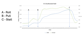
For the non-engineering crowd, remember “the slower you go, the faster you go slower.” This is shown in this figure which shows us how hard the wing is working relative to airspeed. Note that airspeed is decreasing as you read the chart from left to right:

You can see from the plot of AOA vs airspeed, that the wing is doing 75% of its work in the lower half of the speed band of the airplane. At Vref, it is using 60% of its capacity to generate lift, and the requirement for lift increases rapidly as you get slower. This is why it it’s relatively easy for an accelerated stall after takeoff or before landing to catch a pilot off guard.
There is no requirement to have any sort of stall warning or AOA installed in our experimental RV’s. As Paul has eloquently pointed out, it’s a myth that we can fly any airplane by the “seat of our pants.” And we know experience isn’t always a good teacher as just as many experienced pilots die due to loss of control as inexperienced ones. This demonstration shows the small amount of g and adverse yaw (improperly coordinated rudder) that will cause a loss of control in landing configuration in an RV-4 without any buffet cues. Note, however, that the AOA is screaming at the pilot as the airplane approaches stall:
In the demonstration video, a series of tones are used to convey AOA information to the pilot that were first used by the military in the 1970’s. They are based on a simple trend as AOA increases from L/Dmax to stall and sound like this:
If we superimpose the tone pattern over the figure above, it looks like this:

This is what we mean when we assert that AOA has the capability to provide outstanding progressive stall warning. In this case, we simply capture some other key performance parameters as well. We’ll explain this in more depth when we discuss aural cues, but first let’s review some basics in the next post.
Pleasure to meet you. I'm guessing you don't have any F-4 time in a USAF tail? It was the niftiest implementation of AOA I've flown, because the Rhino was so challenged in ACM, especially the hard-winged jets. Interestingly, it originated in the Royal Navy who developed it to come aboard the boat. The USAF also employed it in the F-117 and U-2. We added a pilot selectable audio cue to the F-15 as well to supplement HUD and JHMCS. Uber handy when your eyeballs are anywhere but forward. Also uber handy in the traffic pattern. Truth in advertising, zero point zero Hornet hours--only met you guys at the merge and the bar. Think of AOA tone as a coping mechanism for us folks with silver wings
. You can check out the F-4 dash one (NATOPS) here if you are interested in a description of the system. Should look mighty familiar except for the "non-dimensional cockpit units" McD liked to use and the tone. We won the EAA Founder's Innovation Prize for adopting the tone logic to an accurate, inexpensive coefficient of pressure system built using off-the-shelf parts. Totally agree on magic bullet status for AOA, there is no such thing as a Pk of 1.0, and would like to make Boyd accessible for the masses using the basics of the AOA tone logic to help not only fly the wing, but control power. And all of your math is spot on. Paul, forgive the delayed response—late to the fight, no excuse. For our ONSPEED.org system, we are still working ESP-32 integration, so nothing to report currently as we write the code to go with the new hardware.
As for the AOA system recommendations, which was the original intent of the thread, let's consider a few things:
Short answer:
Start with the one you have if you have an EFIS from any of the major manufacturers that build experimental avionics. All of them include some form of indigenous AOA capability, usually based on differential pressure or IMU-derived AOA. It may be necessary to install the appropriate wing mounted sensor and add an additional tube added to the wing if the original builder did not install a combination pitot/AOA. Some systems will utilize an additional pop rivet, a dedicated AOA sensor, ports in the wing skin or a stagnation sensor on the leading edge of the wing. Some systems use a wing mounted vane. If you don’t have glass, an LRI as described by Fffflats is a good inexpensive alternative, but several other very good stand-alone systems are available (e.g., Alpha Systems and SafeFlight). Ultimately, any AOA (when properly calibrated) is better than no AOA. Read the manual and calibrate your system in accordance with the manufacturer’s instructions. Flight test the system until you gain confidence in its performance. Trust but verify—before you turn base using AOA as a reference, cross check the AOA indication or tone against a known airspeed to confirm proper operation, and then "fly the wing." Flying a precise AOA cue is one of the easiest ways to increase precision and consistency in your landings. A common observation of folks new to AOA is “I’ve been flying too fast” on approach.
Long Answer:
Accuracy and limitations vary by manufacturer as does the technique to measure AOA, but all systems will provide progressive stall warning when properly calibrated. This feature is what makes AOA superior to conventional stall warning by eliminating the startle effect associated with unintentional stall. The “at least five knots” required for conventional “stall horns” (usually designed to meet FAR 23 performance requirements) only works out to a few of degrees actual AOA warning, and as Fffflats points out, AOA increase is non-linear as you slow down. If the stall warning goes off and you are dutifully maintaining Vref, you are within about 1.5-2.0 degrees of actual stall—not much margin for a handling error or gust upset. That math is explained here for those interested in drilling down into the aerodynamics.
For the non-engineering crowd, remember “the slower you go, the faster you go slower.” This is shown in this figure which shows us how hard the wing is working relative to airspeed. Note that airspeed is decreasing as you read the chart from left to right:
You can see from the plot of AOA vs airspeed, that the wing is doing 75% of its work in the lower half of the speed band of the airplane. At Vref, it is using 60% of its capacity to generate lift, and the requirement for lift increases rapidly as you get slower. This is why it it’s relatively easy for an accelerated stall after takeoff or before landing to catch a pilot off guard.
There is no requirement to have any sort of stall warning or AOA installed in our experimental RV’s. As Paul has eloquently pointed out, it’s a myth that we can fly any airplane by the “seat of our pants.” And we know experience isn’t always a good teacher as just as many experienced pilots die due to loss of control as inexperienced ones. This demonstration shows the small amount of g and adverse yaw (improperly coordinated rudder) that will cause a loss of control in landing configuration in an RV-4 without any buffet cues. Note, however, that the AOA is screaming at the pilot as the airplane approaches stall:
In the demonstration video, a series of tones are used to convey AOA information to the pilot that were first used by the military in the 1970’s. They are based on a simple trend as AOA increases from L/Dmax to stall and sound like this:
If we superimpose the tone pattern over the figure above, it looks like this:
This is what we mean when we assert that AOA has the capability to provide outstanding progressive stall warning. In this case, we simply capture some other key performance parameters as well. We’ll explain this in more depth when we discuss aural cues, but first let’s review some basics in the next post.
Attachments
Last edited:
How We Measure AOA
There are three ways to measure AOA: absolute, geometric and body angle. As pilot’s we only care about body angle—the difference between the relative wind and a fuselage reference line. This is essentially the difference between where the airplane is pointed (pitch) and where it’s going (flight path angle). We can use body angle to measure key performance parameters like L/Dmax, on speed (AOA equal to Vref at 1 g) and stall warning. This effectively takes wing geometry (other than flap position) out of the equation while providing a flyable cue. This is an important takeaway—we need to have an AOA calibration for each flap position we normally fly. Some systems accommodate multiple calibrations (requiring the use of some sort of flap sensor) and some don’t. If you have a system with only one calibration curve, it’s best to use your normal landing configuration to calibrate.
Vanes. One way to measure AOA is with a vane that aligns itself with the relative wind as AOA changes. Vanes are, however, problematic on propeller driven airplanes. The best place to mount a vane is on a boom ahead of the nose of the airplane, with the second-best location on the side of the nose. Obviously, when there is a single propeller on the nose, these are not options. Any vane mounted on the wing (either on a boom or under the wing) will be subject to upwash effects, including the change in AOA that occurs in ground effect when we takeoff and land. Although we use a wing mounted vane for flight test, that system is subject to limitations and we must compensate for upwash, pitch rate, roll rate and boom deflection as a result a g-load. In theory, we can eliminate upwash effects if the vane is at least one chord width ahead of the leading edge, but that would mean over 50 inches on a typical RV and you’d still suffer the other effects and would have substantial flexing as well. This is one reason poor AOA performance was observed in a 1975 NASA AOA study occasionally cited by AOA critics. The NASA system used for study also had significant lag (as a result of the primitive computer used) and utilized a horizontal milliampere mechanical indicator prone to error induced by yaw. This display was also non-ergonomic insofar as requiring the pilot to interpret a left/right AOA indication in terms of the requirement for an up/down pitch input. These design limitations resulted in the pilot essentially reacting “out of phase” to AOA—flying a PIO, or “pilot induced oscillation” if you will. Although the later shortcomings (lag, signal processing and display) have been long since overcome with technology, the basic shortcomings of a vane remain. They work well on jets, but not on airplanes with propellers.
On the other hand, a simple mechanical device will essentially look the same or measure the same angle at stall every time, so it can be calibrated to provide stall warning and can be very inexpensive. The earliest example was the string the Wright Brothers used to measure what they called “angle of incidence,” a British expression for AOA. Orville patented a more advanced, strut-mounted mechanical version in 1913, which interestingly sold for the equivalent of about 2000 current dollars. This was the first commercially available AOA indicator and costs about what a stand-alone system does today.
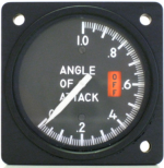
Stagnation Sensor. This is a small vane on the leading edge of the wing that “flops” up and down as the angle of the relative wind changes. Conventional stall warning horns are of this type, and effectively “come on” when the AOA associated with FAR 23 stall warning maneuvering limits are reached. It is practical to calibrate a stagnation sensor to provide a broader band of warning that what is conventionally used for stall warning, typically capturing an on speed (normal approach) condition. The SafeFlight system uses this approach. A clever installation of this type is used by some Cirrus airplanes with advanced glass that display a digital version of a military 0-1 gauge to display AOA (shown in an illustration below) next to the airspeed tape during takeoff and approach. This type of sensor can provide a good on speed cue as well as stall warning. If you’ve flown has a reed sensor (a simple slot in the leading edge), it uses the same principle, when the relative wind hits the leading edge at the right angle, air flows through two reeds to generate a stall warning tone.
IMU-derived AOA. If the EFIS has an AHRS and can compute flight path angle, it’s simple arithmetic to compute the difference between that angle and the pitch angle of the airplane, providing the body angle measurement we need as pilots. However, not all IMU-derived AOA is created equally. To derive an accurate solution, some elegant Kalman filtering of accurate instantaneous vertical velocity is required (that’s the AHRS input, and not all pressure sensors are created equally—some are more accurate than others and not all code uses Kalman filtering). Some elegant matrix calculus is also required in the code for maneuvering flight. Generally, these systems provide reasonable performance at low g (say 2 or less) and low bank angles. The tactical advantage of this approach is that no additional sensor, wiring or plumbing is required. Like any AOA system, they must be calibrated. Another use for IMU-derived AOA is calibration. Our system uses IMU-derived AOA to calibrate pressure-derived AOA for example. The advantage of this automated approach is that calibration accuracy is improved, and cues will be consistent from airplane to airplane, even airplanes of different types.
Differential pressure. While not all systems that use differential pressure perform equally (some only provide progressive stall warning), it’s possible with the right combination of physics, configuration and pressure sensor performance to derive a very accurate solution, especially when measuring differential pressure in the same flow field in the relative free-stream area below the wing, usually about 25-50% chord. Systems that use ports on the top and bottom of the wing or a leading-edge mounted pop rivet will be less accurate than those using a dedicated sensor with co-located pressure ports. The shape of the sensor can be optimized to mitigate high AOA and sideslip effects, and some shapes perform better than others. With the right implementation, it’s practical to measure AOA to within a fraction of a degree across the speed band of the airplane using differential pressure. In within a degree even at high g.
Transient Response
This is an engineering expression that means “how well does everything work when the pilot maneuvers agressively or the airplane encounters turbulence.” AOA is an inherently noisy signal—you can see this with some systems if it’s a bumpy ride down final. It’s practical to damp the AOA signal with the right signal processing and ergonomics, but not all systems do this equally well. Under the same conditions, the airspeed will also be “active” and to provide additional margin, we increase VREF that imparts extra energy we still must dissipate to land. With the right physics and “display” logic (which may be a tone), we can generate a flyable signal that is accurate in a gust of wind or when the pilot makes a rapid flight control input and always detects stall before critical AOA is reached. With adequate transient response, an AOA system will work in gusty conditions and under high g.
That last bit is important, if you pull on the stick (or yoke), you induce g and AOA increases. The same thing happens when you hit a gust load. Here’s an example of a high g accelerated stall near the 6 g-limit of the test airplane. Notice that stall warning occurs before the nose stops tracking across the horizon (accelerated stall):
Here's what it looks like when we plot the g-load and AOA data from that demonstration:

Note in the plot that it takes the air molecules a bit to catch up with the g-load. This relationship between g and AOA holds regardless of how aggressive the maneuvering is. This is just an extreme example that clearly shows what happens in an accelerated stall. Recall in the first video, the accelerated stall occurred at a whopping 1.2-1.3 g’s—g-loads easily encountered in the traffic pattern, to too small to measure even with the most finely tuned pants .
.
What is a Coefficient of Pressure?
This is simply a way to compare something (in this case two different pressures) so you can make a comparison regardless of size or scale. “Normalization” is the process of turning the two raw pressure numbers (in whatever units they are measured in) into a coefficient by dividing by something to set the scale. There are numerous techniques for this, but the dirt simple approach is to divide the offset pressure by the pitot (dynamic) pressure. Depending on the shape of the sensor (which may be a blade, or something that looks like a conventional pitot tube with an additional offset pressure port), sometimes the pressure will change from positive to negative as the angle of the relative wind changes. Fffflats points this out, and we see different characteristics with the numerous different types of probes we have tested. The problem is if the denominator changes from positive to negative (or vice versa), it must go through zero and if you ask a computer to divide by zero, it will go into tilt. We know dynamic pressure is always positive, unless you are in a tail slide, in which case you don’t need accurate AOA . This is a clever engineering hack that when combined with an accurate differential pressure sensor (say +/- 1 PSI with less than 1% error), a decent enough CPU to divide to seven significant digits and then filter the result at high speed; you can achieve impressive accuracy.
What’s nifty about this, is that this coefficient changes with AOA, and ALWAYS peaks at stall, regardless of sideslip angle, ground effect or pitch rate. This is a very cool concept, that means we’ll always get good progressive stall warning from a system, even if the accuracy of the AOA solution is a little “off” due to an aerodynamic effect. A good example is takeoff and landing. The actual AOA at which the wing stalls (critical angle of attack) changes in ground effect. If we were to measure AOA using a vane, we’d need a separate “ground effect” calibration to detect stall in ground effect; but a coefficient of pressure system “auto regulates” and on speed always occurs when the wing is at 60% peak coefficient of pressure. Another good example is when the airplane has significant side slip angle. Side slip will induce error in both airspeed and AOA measured using pressure. Here’s an interesting demonstration of a series of oscillating stalls with significant side slip on the airplane. Note at each stall, the system accurately warns the pilot and provides stall warning despite the significant sideslip angle:
Visual Indicators
Visual indicators are all over the map, and all require the pilot to look at them and process the information displayed. Some are simple gauges marked in “non-dimensional” units. A good example is the classic 0-1 display, where an on speed condition occurs at .6. The military has used this type of gauge since AOA was first adopted, and regardless of “units,” the gauge was rotated (or designed) so that an on speed (normal approach) condition was at right 3 o’clock as shown here:

Note that if an airspeed indicator is properly sized for the speed band of the airplane, at VREF the needle will be at approximately three o’clock as well. The technique Fffflats described for rotating the LRI in the glare shield is similar and quite clever. A good friend had a similar installation in his RV-8 that worked quite well.
Perhaps the most intuitive visual indicator is that used in the ICON amphibian that was certified as a light sport airplane. A simple depiction of a wing that rotates up and down with AOA and uses a color-coded band to depict on speed, slow and stall warning. Brilliant. Several displays use some combinations of colored bars and chevrons. The most classic (and easiest to interpret) “doughnut/chevron” display is the military one, which consists of two chevrons and a doughnut in the middle. The chevron that is lit shows the pilot which way to move the stick to achieve on speed, which occurs when just the doughnut is lit. “Slightly fast” or “slow” conditions light both the chevron and doughnut. Intuitive after you’ve seen it in action, and the USAF and USN can’t agree on colors The basic F-18 display is shown here. Note that the military refers to the visual AOA display as an “indexer.”

A lack of standardization in visual displays is one of the current issues with AOA implementation. Combine this with a lack of performance standards and differences in display because of variations of calibrations performed in the field and you can see we have a way to go integrating AOA into GA. We are still in the beta-max vs VHS phase of implementation but progressing rapidly. If there is one solid lesson to draw from over half a century of military use of AOA, it’s the concept of “on speed” and we might consider calling a visual indictor that uses graphics an “AOA indexer” to avoid re-inventing a couple of wheels.
Tone or Audio Warning
Like visual displays, there is no current standard for aural cues. Aural cues have the advantage of not requiring the pilot to look at anything. One of the most intuitive is the tone the USAF used in the F-4, F-117 and U-2. All these airplanes shared a common characteristic: challenging handling characteristics, with the F-4 being particularly prone to loss of control. The AOA tone provides simple intuitive feedback and doesn’t require any training. It simply tells the pilot whether the airplane is on speed, or “fast” or “slow” relative to that desired condition. A fast tone is heard when the lower chevron is lit, a steady tone when the airplane is on speed and a slow tone is heard if the upper chevron is lit. A variable pulse rate and change of frequency tells the pilot “a little slow” or “way fast.” This results in a simple push/pull matrix for the pilot to execute.
Some pilots find it odd the military calls optimum AOA for approach “on speed” and we use the expression “fast” or “slow” when we are really talking about an angle. This is done for ergonomic reasons, and ultimately the term on speed means “at the appropriate airspeed to maintain desired AOA” since that speed varies with weight and g-load (i.e., any time we maneuver). As pilots, we are wired for thinking in terms of speed anyway and we “fix” slow by pushing something, either the stick or the throttle, or both and fix fast by pulling something. This simple tone pattern also has the advantage of allowing for signal processing and uses a small range of angles (about +/- 1 deg for the typical GA airplane) to mitigate the “noise” inherent with trying to fly a specific AOA. The on speed cue is a small range of airspeeds—about +/- 2.5 knots of Vref at 1 g. This pattern provides trend information and a flyable cue. This is different from current FAA taxonomy where an aural cue is associated with a bad condition. An on speed or fast cue is a good condition. Although it’s possible to turn off various portions of the pattern, that limits the trend information to pilot and they’re ability to make precise corrections. There has also been discussion of eliminating the tone when on speed—i.e., no tone = good. The only problem with this approach is that the pilot has no aural indication of system failure. The tone itself provides constant feedback to the pilot that the system is working.
Fly safe,
Vac
There are three ways to measure AOA: absolute, geometric and body angle. As pilot’s we only care about body angle—the difference between the relative wind and a fuselage reference line. This is essentially the difference between where the airplane is pointed (pitch) and where it’s going (flight path angle). We can use body angle to measure key performance parameters like L/Dmax, on speed (AOA equal to Vref at 1 g) and stall warning. This effectively takes wing geometry (other than flap position) out of the equation while providing a flyable cue. This is an important takeaway—we need to have an AOA calibration for each flap position we normally fly. Some systems accommodate multiple calibrations (requiring the use of some sort of flap sensor) and some don’t. If you have a system with only one calibration curve, it’s best to use your normal landing configuration to calibrate.
Vanes. One way to measure AOA is with a vane that aligns itself with the relative wind as AOA changes. Vanes are, however, problematic on propeller driven airplanes. The best place to mount a vane is on a boom ahead of the nose of the airplane, with the second-best location on the side of the nose. Obviously, when there is a single propeller on the nose, these are not options. Any vane mounted on the wing (either on a boom or under the wing) will be subject to upwash effects, including the change in AOA that occurs in ground effect when we takeoff and land. Although we use a wing mounted vane for flight test, that system is subject to limitations and we must compensate for upwash, pitch rate, roll rate and boom deflection as a result a g-load. In theory, we can eliminate upwash effects if the vane is at least one chord width ahead of the leading edge, but that would mean over 50 inches on a typical RV and you’d still suffer the other effects and would have substantial flexing as well. This is one reason poor AOA performance was observed in a 1975 NASA AOA study occasionally cited by AOA critics. The NASA system used for study also had significant lag (as a result of the primitive computer used) and utilized a horizontal milliampere mechanical indicator prone to error induced by yaw. This display was also non-ergonomic insofar as requiring the pilot to interpret a left/right AOA indication in terms of the requirement for an up/down pitch input. These design limitations resulted in the pilot essentially reacting “out of phase” to AOA—flying a PIO, or “pilot induced oscillation” if you will. Although the later shortcomings (lag, signal processing and display) have been long since overcome with technology, the basic shortcomings of a vane remain. They work well on jets, but not on airplanes with propellers.
On the other hand, a simple mechanical device will essentially look the same or measure the same angle at stall every time, so it can be calibrated to provide stall warning and can be very inexpensive. The earliest example was the string the Wright Brothers used to measure what they called “angle of incidence,” a British expression for AOA. Orville patented a more advanced, strut-mounted mechanical version in 1913, which interestingly sold for the equivalent of about 2000 current dollars. This was the first commercially available AOA indicator and costs about what a stand-alone system does today.
Stagnation Sensor. This is a small vane on the leading edge of the wing that “flops” up and down as the angle of the relative wind changes. Conventional stall warning horns are of this type, and effectively “come on” when the AOA associated with FAR 23 stall warning maneuvering limits are reached. It is practical to calibrate a stagnation sensor to provide a broader band of warning that what is conventionally used for stall warning, typically capturing an on speed (normal approach) condition. The SafeFlight system uses this approach. A clever installation of this type is used by some Cirrus airplanes with advanced glass that display a digital version of a military 0-1 gauge to display AOA (shown in an illustration below) next to the airspeed tape during takeoff and approach. This type of sensor can provide a good on speed cue as well as stall warning. If you’ve flown has a reed sensor (a simple slot in the leading edge), it uses the same principle, when the relative wind hits the leading edge at the right angle, air flows through two reeds to generate a stall warning tone.
IMU-derived AOA. If the EFIS has an AHRS and can compute flight path angle, it’s simple arithmetic to compute the difference between that angle and the pitch angle of the airplane, providing the body angle measurement we need as pilots. However, not all IMU-derived AOA is created equally. To derive an accurate solution, some elegant Kalman filtering of accurate instantaneous vertical velocity is required (that’s the AHRS input, and not all pressure sensors are created equally—some are more accurate than others and not all code uses Kalman filtering). Some elegant matrix calculus is also required in the code for maneuvering flight. Generally, these systems provide reasonable performance at low g (say 2 or less) and low bank angles. The tactical advantage of this approach is that no additional sensor, wiring or plumbing is required. Like any AOA system, they must be calibrated. Another use for IMU-derived AOA is calibration. Our system uses IMU-derived AOA to calibrate pressure-derived AOA for example. The advantage of this automated approach is that calibration accuracy is improved, and cues will be consistent from airplane to airplane, even airplanes of different types.
Differential pressure. While not all systems that use differential pressure perform equally (some only provide progressive stall warning), it’s possible with the right combination of physics, configuration and pressure sensor performance to derive a very accurate solution, especially when measuring differential pressure in the same flow field in the relative free-stream area below the wing, usually about 25-50% chord. Systems that use ports on the top and bottom of the wing or a leading-edge mounted pop rivet will be less accurate than those using a dedicated sensor with co-located pressure ports. The shape of the sensor can be optimized to mitigate high AOA and sideslip effects, and some shapes perform better than others. With the right implementation, it’s practical to measure AOA to within a fraction of a degree across the speed band of the airplane using differential pressure. In within a degree even at high g.
Transient Response
This is an engineering expression that means “how well does everything work when the pilot maneuvers agressively or the airplane encounters turbulence.” AOA is an inherently noisy signal—you can see this with some systems if it’s a bumpy ride down final. It’s practical to damp the AOA signal with the right signal processing and ergonomics, but not all systems do this equally well. Under the same conditions, the airspeed will also be “active” and to provide additional margin, we increase VREF that imparts extra energy we still must dissipate to land. With the right physics and “display” logic (which may be a tone), we can generate a flyable signal that is accurate in a gust of wind or when the pilot makes a rapid flight control input and always detects stall before critical AOA is reached. With adequate transient response, an AOA system will work in gusty conditions and under high g.
That last bit is important, if you pull on the stick (or yoke), you induce g and AOA increases. The same thing happens when you hit a gust load. Here’s an example of a high g accelerated stall near the 6 g-limit of the test airplane. Notice that stall warning occurs before the nose stops tracking across the horizon (accelerated stall):
Here's what it looks like when we plot the g-load and AOA data from that demonstration:
Note in the plot that it takes the air molecules a bit to catch up with the g-load. This relationship between g and AOA holds regardless of how aggressive the maneuvering is. This is just an extreme example that clearly shows what happens in an accelerated stall. Recall in the first video, the accelerated stall occurred at a whopping 1.2-1.3 g’s—g-loads easily encountered in the traffic pattern, to too small to measure even with the most finely tuned pants
.What is a Coefficient of Pressure?
This is simply a way to compare something (in this case two different pressures) so you can make a comparison regardless of size or scale. “Normalization” is the process of turning the two raw pressure numbers (in whatever units they are measured in) into a coefficient by dividing by something to set the scale. There are numerous techniques for this, but the dirt simple approach is to divide the offset pressure by the pitot (dynamic) pressure. Depending on the shape of the sensor (which may be a blade, or something that looks like a conventional pitot tube with an additional offset pressure port), sometimes the pressure will change from positive to negative as the angle of the relative wind changes. Fffflats points this out, and we see different characteristics with the numerous different types of probes we have tested. The problem is if the denominator changes from positive to negative (or vice versa), it must go through zero and if you ask a computer to divide by zero, it will go into tilt. We know dynamic pressure is always positive, unless you are in a tail slide, in which case you don’t need accurate AOA
. This is a clever engineering hack that when combined with an accurate differential pressure sensor (say +/- 1 PSI with less than 1% error), a decent enough CPU to divide to seven significant digits and then filter the result at high speed; you can achieve impressive accuracy.What’s nifty about this, is that this coefficient changes with AOA, and ALWAYS peaks at stall, regardless of sideslip angle, ground effect or pitch rate. This is a very cool concept, that means we’ll always get good progressive stall warning from a system, even if the accuracy of the AOA solution is a little “off” due to an aerodynamic effect. A good example is takeoff and landing. The actual AOA at which the wing stalls (critical angle of attack) changes in ground effect. If we were to measure AOA using a vane, we’d need a separate “ground effect” calibration to detect stall in ground effect; but a coefficient of pressure system “auto regulates” and on speed always occurs when the wing is at 60% peak coefficient of pressure. Another good example is when the airplane has significant side slip angle. Side slip will induce error in both airspeed and AOA measured using pressure. Here’s an interesting demonstration of a series of oscillating stalls with significant side slip on the airplane. Note at each stall, the system accurately warns the pilot and provides stall warning despite the significant sideslip angle:
Visual Indicators
Visual indicators are all over the map, and all require the pilot to look at them and process the information displayed. Some are simple gauges marked in “non-dimensional” units. A good example is the classic 0-1 display, where an on speed condition occurs at .6. The military has used this type of gauge since AOA was first adopted, and regardless of “units,” the gauge was rotated (or designed) so that an on speed (normal approach) condition was at right 3 o’clock as shown here:
Note that if an airspeed indicator is properly sized for the speed band of the airplane, at VREF the needle will be at approximately three o’clock as well. The technique Fffflats described for rotating the LRI in the glare shield is similar and quite clever. A good friend had a similar installation in his RV-8 that worked quite well.
Perhaps the most intuitive visual indicator is that used in the ICON amphibian that was certified as a light sport airplane. A simple depiction of a wing that rotates up and down with AOA and uses a color-coded band to depict on speed, slow and stall warning. Brilliant. Several displays use some combinations of colored bars and chevrons. The most classic (and easiest to interpret) “doughnut/chevron” display is the military one, which consists of two chevrons and a doughnut in the middle. The chevron that is lit shows the pilot which way to move the stick to achieve on speed, which occurs when just the doughnut is lit. “Slightly fast” or “slow” conditions light both the chevron and doughnut. Intuitive after you’ve seen it in action, and the USAF and USN can’t agree on colors
The basic F-18 display is shown here. Note that the military refers to the visual AOA display as an “indexer.”A lack of standardization in visual displays is one of the current issues with AOA implementation. Combine this with a lack of performance standards and differences in display because of variations of calibrations performed in the field and you can see we have a way to go integrating AOA into GA. We are still in the beta-max vs VHS phase of implementation
but progressing rapidly. If there is one solid lesson to draw from over half a century of military use of AOA, it’s the concept of “on speed” and we might consider calling a visual indictor that uses graphics an “AOA indexer” to avoid re-inventing a couple of wheels.Tone or Audio Warning
Like visual displays, there is no current standard for aural cues. Aural cues have the advantage of not requiring the pilot to look at anything. One of the most intuitive is the tone the USAF used in the F-4, F-117 and U-2. All these airplanes shared a common characteristic: challenging handling characteristics, with the F-4 being particularly prone to loss of control. The AOA tone provides simple intuitive feedback and doesn’t require any training. It simply tells the pilot whether the airplane is on speed, or “fast” or “slow” relative to that desired condition. A fast tone is heard when the lower chevron is lit, a steady tone when the airplane is on speed and a slow tone is heard if the upper chevron is lit. A variable pulse rate and change of frequency tells the pilot “a little slow” or “way fast.” This results in a simple push/pull matrix for the pilot to execute.
Some pilots find it odd the military calls optimum AOA for approach “on speed” and we use the expression “fast” or “slow” when we are really talking about an angle. This is done for ergonomic reasons, and ultimately the term on speed means “at the appropriate airspeed to maintain desired AOA” since that speed varies with weight and g-load (i.e., any time we maneuver). As pilots, we are wired for thinking in terms of speed anyway and we “fix” slow by pushing something, either the stick or the throttle, or both and fix fast by pulling something. This simple tone pattern also has the advantage of allowing for signal processing and uses a small range of angles (about +/- 1 deg for the typical GA airplane) to mitigate the “noise” inherent with trying to fly a specific AOA. The on speed cue is a small range of airspeeds—about +/- 2.5 knots of Vref at 1 g. This pattern provides trend information and a flyable cue. This is different from current FAA taxonomy where an aural cue is associated with a bad condition. An on speed or fast cue is a good condition. Although it’s possible to turn off various portions of the pattern, that limits the trend information to pilot and they’re ability to make precise corrections. There has also been discussion of eliminating the tone when on speed—i.e., no tone = good. The only problem with this approach is that the pilot has no aural indication of system failure. The tone itself provides constant feedback to the pilot that the system is working.
Fly safe,
Vac
Last edited:
Vac, I appreciate your enthusiasm and your very detailed and thorough analysis but you just wrote a book on the VAF forum! I read everything you post but holy cow that was pretty lengthy. I flew A-10s & F-16s in the military and have a Dynon AOA in my RV-8 and it has a progressive AOA that is hugely helpful for L/D Max maneuvering and for landing. I never look inside at the AOA indicator, I just listen to the tones. AOA saved my life one time in the A-10. We were on a low level at 300’ and ended up in a low altitude furball in Germany in the 80s (when there were no rules) with German F-4s that had snuck up on us (because they were at 100’) and we did our usual bat turns and were quickly out of energy. I was pretty much at treetop level after a couple turns from our usual 300’ low levels. I very gently milked the stick on the AOA tones and just missed the trees - I actually had my left hand on the ejection handle. So do I believe in AOA? ABSOLUTELY so everything Vac says is true and his system is spot on. So you naysayers of AOA I leave you with this one thought I heard at a Red Flag debrief once by a guy named Steve Grimstead- He was talking about Close Air Support (CAS) and said, “CAS is like S&M, you don’t know how good it is till you’ve tried it”. So for all you non AOA believers I leave you with this, “You don’t know how good AOA is until you’ve tried it”.
Last edited:
dynon grt and garmin all use a calibration process to determine stall aoa. I believe it simply grabs the highest or lowest indication while performing a stall and recovery. It can’t be as simple as zero, otherwise calibration wouldn’t be necessary. I also thought the 4 6 7 8 wings stalled around 22 or 23*Another way to think of it is if the difference between pressures at stall is zero, doesn’t matter if both are 65, 145, or 400. Twice stall angle for port angle makes for zeroized difference between the ports at stall as they’ll have equal ram components at stall. This is why the Dynon, and I would assume Garmin, dual pitot-AOA is at 36 degrees between ports. 18 is very likely near your critical angle.
Fffflats
Well Known Member
No, they’re not zero, but if you could move your probe alignment, and if the angle between ports be twice critical angle, then you could make it so both ports have equal pressure at critical angle which would easily eliminate the accelerated stall gauge reading error. You won’t be able to do such things with Garmin nor Dynon. Nor most probes. Hence you should realize you may stall at high g at a lower indication than what you think is critical angle. Critical angle is the same but its display is not. Electronic devices could (but might not) crunch math to resolve, but simple devices can’t. As for what this critical angle actually is, I don’t know what its value is. Though watch for an angle of incidence or angle between chord and longitudinal axis which would make airframe critical value different than wing critical value. (Note this is a different definition and use of term than Wrights used.)dynon grt and garmin all use a calibration process to determine stall aoa. I believe it simply grabs the highest or lowest indication while performing a stall and recovery. It can’t be as simple as zero, otherwise calibration wouldn’t be necessary. I also thought the 4 6 7 8 wings stalled around 22 or 23*
Thanks for the clarification.No, they’re not zero, but if you could move your probe alignment, and if the angle between ports be twice critical angle, then you could make it so both ports have equal pressure at critical angle which would easily eliminate the accelerated stall gauge reading error. You won’t be able to do such things with Garmin nor Dynon. Nor most probes. Hence you should realize you may stall at high g at a lower indication than what you think is critical angle. Critical angle is the same but its display is not. Electronic devices could (but might not) crunch math to resolve, but simple devices can’t. As for what this critical angle actually is, I don’t know what its value is. Though watch for an angle of incidence or angle between chord and longitudinal axis which would make airframe critical value different than wing critical value. (Note this is a different definition and use of term than Wrights used.)
This has got me re-thinking how I set up my 10. The kit came with a new gretz heated pitot, so thought I would save the $ and not buy the garmin probe for my G3X. I mounted a BLF rivet on the lower side of the LE. I got some insight from Scott on how it was done on the 12. It calibrates well and stall seems to coincide with the indication pretty closely, though my experience and flying skills are FAR from your level (I do love watching your videos and aspire to achieve your skill level some day). I have the ability to move this rivet around to optimize. I could also purchase a dynon or garmin probe. Any reason to think that this installation is sub-optimal enough in my application to warrant a change? This is a cross country machine, so doesn't get thrown around for fun, like the 6. Just want reliable warnings in slow flight and landing phase, That said, low G accelerated stalls are always a present danger in the pattern, as you showed us.Differential pressure. While not all systems that use differential pressure perform equally (some only provide progressive stall warning), it’s possible with the right combination of physics, configuration and pressure sensor performance to derive a very accurate solution, especially when measuring differential pressure in the same flow field in the relative free-stream area below the wing, usually about 25-50% chord. Systems that use ports on the top and bottom of the wing or a leading-edge mounted pop rivet will be less accurate than those using a dedicated sensor with co-located pressure ports. The shape of the sensor can be optimized to mitigate high AOA and sideslip effects, and some shapes perform better than others. With the right implementation, it’s practical to measure AOA to within a fraction of a degree across the speed band of the airplane using differential pressure. In within a degree even at high g.
Fly safe,
Vac
Fffflats
Well Known Member
Probably not worth the effort. Have you read the Medium piece referenced above Improve your Landings with AOA and Power Techniques? Be worth while. You can’t pattern stall even that little bit if you don’t pull. (We really should teach constant AOA turns instead of constant airspeed in slow flight.) Does your display give you some sort of AOAref for your approach? Or have you noted where such occurs? How far is the range of your display? Have Best Glide plotted? Maximum endurance. Max range (in still air)? (Though likely you’ll fly faster for convenience sake.) See also the Medium case study F-35C Crash into the South China Sea and the somewhat associated Power Curve vs Drag Curve pieces.This has got me re-thinking how I set up my 10. The kit came with a new gretz heated pitot, so thought I would save the $ and not buy the garmin probe for my G3X. I mounted a BLF rivet on the lower side of the LE. I got some insight from Scott on how it was done on the 12. It calibrates well and stall seems to coincide with the indication pretty closely, though my experience and flying skills are FAR from your level (I do love watching your videos and aspire to achieve your skill level some day). I have the ability to move this rivet around to optimize. I could also purchase a dynon or garmin probe. Any reason to think that this installation is sub-optimal enough in my application to warrant a change? This is a cross country machine, so doesn't get thrown around for fun, like the 6. Just want reliable warnings in slow flight and landing phase, That said, low G accelerated stalls are always a present danger in the pattern, as you showed us.
Yes, the garmin gives the doughnut for Vref and when I calibrated, I picked 1.4 as the vref. I have not tested it though. Any recommendations for testing it? is it just flyiny at 1.4 full flap stall speed with flaps engaged and insuring I get the doughnut at that speed?Probably not worth the effort. Have you read the Medium piece referenced above Improve your Landings with AOA and Power Techniques? Be worth while. You can’t pattern stall even that little bit if you don’t pull. (We really should teach constant AOA turns instead of constant airspeed in slow flight.) Does your display give you some sort of AOAref for your approach? Or have you noted where such occurs? How far is the range of your display? Have Best Glide plotted? Maximum endurance. Max range (in still air)? (Though likely you’ll fly faster for convenience sake.) See also the Medium case study F-35C Crash into the South China Sea and the somewhat associated Power Curve vs Drag Curve pieces.
Fffflats
Well Known Member
Do the stall, immediately do the math based on present condition stall speed (also double check stall matches where stall should be on indicator), then check your donut. That way should you be light, you won’t be looking for the wrong values. I’m going to guess you’re pretty solid with it though. Do you predominantly do wheel or point landings? If you do point, you’ll likely want to note for yourself to go a touch faster than donut when doing wheel. Does your system compensate for flap settings? If so, same checks for other settings. If not, same checks but make reference where things occur so you have an idea should you need such. Would also recommend power off stalls for the checks but repeat power on to ensure those occur at or at higher indications; you’d want to note if they for some strange reason were lower (probe too close inboard catching wash perhaps?).Yes, the garmin gives the doughnut for Vref and when I calibrated, I picked 1.4 as the vref. I have not tested it though. Any recommendations for testing it? is it just flyiny at 1.4 full flap stall speed with flaps engaged and insuring I get the doughnut at that speed?
The garmin is on my 10, so all landings are wheel landings. I also have a 6A, so nose high landings are deeply engrained.Do the stall, immediately do the math based on present condition stall speed (also double check stall matches where stall should be on indicator), then check your donut. That way should you be light, you won’t be looking for the wrong values. I’m going to guess you’re pretty solid with it though. Do you predominantly do wheel or point landings? If you do point, you’ll likely want to note for yourself to go a touch faster than donut when doing wheel. Does your system compensate for flap settings? If so, same checks for other settings. If not, same checks but make reference where things occur so you have an idea should you need such. Would also recommend power off stalls for the checks but repeat power on to ensure those occur at or at higher indications; you’d want to note if they for some strange reason were lower (probe too close inboard catching wash perhaps?).
Thanks for the tips. I play with this on my next flight.
Hey Ollie, good to hear from you! Never pass up a chance for academics. Obviously, I’ve never been accused of being short-winded  . AOA has saved my bacon in the low-altitude environment as well, and I’m fortunate to still be typing years later.
LR172, Fffflats advice is solid. The way you’ve implemented AOA is clever—that’s what experimental aviation is all about! To answer your question, changing to the actual Garmin probe may improve overall performance, simply because the algorithm is optimized for pressure information from the same flow field (i.e., both ports in the same location); but before you do that, follow Fffflats advice to fly some “Vref tests” to see how your current performance is, it may suit your needs just fine. Only thing I would suggest is to bias on speed to 1.3 Vs instead of 1.4. Depending on airplane, it will usually be between 1.25 and 1.35 Vs. If it's bumpy, you can always flight "slightly fast" just under the doughnut.
If you’re comfortable with stalls, go out to the area, stall and compute Vref by noting IAS at stall and multiplying by 1.3. Then fly that IAS at 1 g and compare it to your AOA indication. If the indexer (visual display) shows on speed, great--then you can check stall warning by flying a 40-45 degree bank in level flight, which will give you 1.4 g’s. At that g-load, you should be about 2 degrees below stall and about 5 knots from stall speed adjusted for g. If everything is working under these two conditions, you’ve got a good calibration “curve” from on speed down thru stall. Since the Garmin has two flap settings/calibrations, your call if you want Flaps 0 and Flaps 30; or takeoff flaps and Flaps 30 calibrations. My suggestion would be takeoff flaps and 30--that covers to the two "high risk" areas: takeoff and landing.
Even with the dedicated probe, the Garmin system appears to be optimized for on speed and slower performance. In other words, any “fast” cues are non-linear. Which means you quickly go from lower bar lit to the doughnut, but then things will slow down and become more aligned with your pitch inputs on the slow side--to a point; because the “slower you go, the faster you go slower”. Any slow indication (assuming you have an accurate on speed cue) means you are on the back side of the power curve and need to reduce AOA, add power or a bit of both. This observation is based on plotting recorded Garmin data in one of our test airplanes and comparing it to some other data sources we have on board.
Fly safe,
Vac
. AOA has saved my bacon in the low-altitude environment as well, and I’m fortunate to still be typing years later.LR172, Fffflats advice is solid. The way you’ve implemented AOA is clever—that’s what experimental aviation is all about! To answer your question, changing to the actual Garmin probe may improve overall performance, simply because the algorithm is optimized for pressure information from the same flow field (i.e., both ports in the same location); but before you do that, follow Fffflats advice to fly some “Vref tests” to see how your current performance is, it may suit your needs just fine. Only thing I would suggest is to bias on speed to 1.3 Vs instead of 1.4. Depending on airplane, it will usually be between 1.25 and 1.35 Vs. If it's bumpy, you can always flight "slightly fast" just under the doughnut.
If you’re comfortable with stalls, go out to the area, stall and compute Vref by noting IAS at stall and multiplying by 1.3. Then fly that IAS at 1 g and compare it to your AOA indication. If the indexer (visual display) shows on speed, great--then you can check stall warning by flying a 40-45 degree bank in level flight, which will give you 1.4 g’s. At that g-load, you should be about 2 degrees below stall and about 5 knots from stall speed adjusted for g. If everything is working under these two conditions, you’ve got a good calibration “curve” from on speed down thru stall. Since the Garmin has two flap settings/calibrations, your call if you want Flaps 0 and Flaps 30; or takeoff flaps and Flaps 30 calibrations. My suggestion would be takeoff flaps and 30--that covers to the two "high risk" areas: takeoff and landing.
Even with the dedicated probe, the Garmin system appears to be optimized for on speed and slower performance. In other words, any “fast” cues are non-linear. Which means you quickly go from lower bar lit to the doughnut, but then things will slow down and become more aligned with your pitch inputs on the slow side--to a point; because the “slower you go, the faster you go slower
”. Any slow indication (assuming you have an accurate on speed cue) means you are on the back side of the power curve and need to reduce AOA, add power or a bit of both. This observation is based on plotting recorded Garmin data in one of our test airplanes and comparing it to some other data sources we have on board.Fly safe,
Vac
Last edited:
Thanks so much for the detailed explanation. I will try these things. I don’t believe the garmin will account foflap position in aoa display. I wonder if that is something that was added in the touch version that I don’t have.Hey Ollie, good to hear from you! Never pass up a chance for academics. Obviously, I’ve never been accused of being short-winded
LR172, Fffflats advice is solid. The way you’ve implemented AOA is clever—that’s what experimental aviation is all about! To answer your question, changing to the actual Garmin probe may improve overall performance, simply because the algorithm is optimized for pressure information from the same flow field (i.e., both ports in the same location); but before you do that, follow Fffflats advice to fly some “Vref tests” to see how your current performance is, it may suit your needs just fine, only thing I would suggest is to bias on speed to 1.3 Vs instead of 1.4. Depending on airplane, it will usually be between 1.25 and 1.35 Vs to give you a usable 5 knot band of airspeed. If it's bumpy, you can always flight "slightly fast" just under the doughnut.
If you’re comfortable with stalls, go out to the area, stall and compute Vref by noting IAS at stall and multiplying by 1.3. Then fly that IAS at 1 g and compare it to your AOA indication. If the indexer (visual display) shows on speed, great--then you can check stall warning by flying a 40-45 degree bank in level flight, which will give you 1.4 g’s. At that g-load, you should be about 2 degrees below stall and about 5 knots from stall speed adjusted for g. If everything is working under these two conditions, you’ve got a good calibration “curve” from on speed down thru stall. Since the Garmin has two flap settings/calibrations, your call if you want Flaps 0 and Flaps 30; or takeoff flaps and Flaps 30 calibrations. My suggestion would be takeoff flaps and 30--that covers to the two "high risk" areas: takeoff and landing.
Even with the dedicated probe, the Garmin system appears to be optimized for on speed and slower performance. In other words, any “fast” cues are non-linear. Which means you quickly go from lower bar lit to the doughnut, but then things will slow down and become more aligned with your pitch inputs on the slow side--to a point; because the “slower you go, the faster you go slower
Fly safe,
Vac
In case you didn’t correlate my handle here, i am the guy that made your tail stand.
Larry
Fffflats
Well Known Member
I’ve had some sidebar communications with Vac now and I wanted to take a moment to say, I was wrong about the origin of tones. Yes, the F-4 did a wonderful thing. I still would not credit the fighter community for it as really this is the smaller F-4 subset and the subset should get credit. In the conversations, I’ve had some other thoughts. These have to do with takeoff.
Generally AOA is useless for the actual takeoff. By this I mean power up through rotation. After rotation, AOA is great. But the same difference between true AOA and pressure differential systems that created vulnerability for errors in accelerated stall readings actually create value for the ground roll for the pressure derived systems. Below are my comments to these notions which I think belong to the wider audience hence this posting:
The takeoff discussion is one that actually gets a bit complicated. Consider a tricycle gear plane, your ground roll is entirely at zero AOA. Similarly, for the tailwheel, you’re at zero AOA after lifting the tail (I like calling going ‘on step’ to match float planes). Prior to this, your AOA was your sitting angle. AOA gives you nothing for when to rotate. It is only after rotation that AOA provides you data though it is different in ground effect (IGE) both for pressure systems pressure distribution being measured and for all systems in that the IGE needs are different. I like AOA for missed approaches, wave-off / go arounds, and mostly for rejected landings though if you’ve rolled a bit when deciding it is balked, you may find similar concern to initial take off. Now, for these takeoffs and smaller set of rejected landings, you aren’t likely staying IGE and if you are you aren’t necessarily needing the AOA feedback accuracy as you’re using the IGE to rapidly change AOA to faster. All you need in IGE is to know rate of change in AOA, not a precise specific value. No or little change or change in the wrong direction makes for a warning indication. But, for the ground roll itself, AOA is no help. Thus we need to break takeoff into pieces. Note I would add a low speed portion to the takeoff roll, most GA fail to distinguish low and high speed abort nor to have differing criteria for each. Well, in that low speed portion, you actually have great opportunity to see your AOA is working. As you turn into the wind (onto the runway), or start making wind on calm days, your AOA should drive down to zero. On the carrier, we’d see this hooking into the catapult, and if we didn’t, we were a suspend and abort. Later, and after a near miss, we took this same approach to field launches, if you don’t see AOA drive down in initial ground roll, abort. But, we were also fly-by-wire with an AOA driven computer. What you’d really want to drive home here is expected AOA responses throughout so as to have baseline comparison to recognize abnormalities. Normal takeoff AOA drives down on roll, jumps up with rotation, slowly reduces as we accelerate in our climb (this acceleration should be more than the IGE to out of ground effect increase, hence we shouldn’t see such), then hold steady at a climb value. Zoom climb would see initial drive down, rotate step increase followed by drive down followed by step and continuing to increase with zoom initiation and zooming to steady climb value. Soft field will be similar to zoom. Non-zoom ‘standard’ short field with obstacle should go to onspeed after rotation then ease lower.
Note Aerodynamics for Naval Aviators discusses early liftoff in several sections, some relevant quotes have been added to the end of paper, while the Canard Boulevard YouTube had an excellent example of such a case.
Bottom line AOA becomes useful after rotation but you’re still using speed to rotate and such should be explicitly acknowledged.
But Pressure Systems, not true AOA as with vanes [stagnation point systems also lose out here]… A caveat to the takeoff discussion I missed is that while your actual AOA is zero during takeoff roll, the pressure system will actually show a decreasing value through acceleration as the front ram hole gets more than the more downward ram hole. Similarly, upper / lower wing pressure systems will also show a ramping downward as, while the shape won’t change, the intensities will [this will be an IGE pattern of changing intensity hence may need different reference values]. Hence, pressure based systems actually have an advantage in takeoff roll as compared to true vane systems. As yours is aimed predominantly at pressure based audiences, you can take advantage of this to not only check system function in ground roll, and also actually use the system throughout takeoff. Interesting systems design aspect I had not considered. That which created vulnerability to accelerated stall actually creates value here, and the fix to accelerated stall indications does not hurt it here.
Now I have not tried these in takeoff, I still use speed during ground roll. But it is something I think I will be exploring in the near future.
Fffflats
Well Known Member
Looks like Vac beat me to this observation and experimenting too: https://www.flyonspeed.org/takeoff-and-landing-using-aural-aoaNow I have not tried these in takeoff, I still use speed during ground roll. But it is something I think I will be exploring in the near future.

Guys, highly informative conversation! After looking at the Dynon Skyview system in a hangar neighbor's Zenair, I am going to install that system with the AOA probe and maybe even Otto if I can save enough pennies. The electric turn and bank will be retired and replaced with a small tequila glass. Many thanks,Rick
Attachments
vlittle
Well Known Member
In support of the OnSpeed system, I now have available a dedicated sunlight-readable energy display that fits in a standard 2” or 3” instrument hole. It can also be mounted on a glareshield with a simple bracket.
It is a stock huVVer-AVI MFD, running a version of the OnSpeed display code. For the technically inclined, this code is publically available on github here https://github.com/huVVer/OnSpeed_huVVer_display.
The huVVer devices are available from MakerPlane. https://makerplane.org/
Note: the standard flight instruments software provided with the huVVer devices also incorporates a version of the OnSpeed energy display. The link above is a streamlined version, much easier to modify for developers of customized applications.
Cheers, Vern
Nice looking display! Thanks for the heads up on the AoA system. Looks like a amazing system...In support of the OnSpeed system, I now have available a dedicated sunlight-readable energy display that fits in a standard 2” or 3” instrument hole. It can also be mounted on a glareshield with a simple bracket.
It is a stock huVVer-AVI MFD, running a version of the OnSpeed display code. For the technically inclined, this code is publically available on github here https://github.com/huVVer/OnSpeed_huVVer_display.
The huVVer devices are available from MakerPlane. https://makerplane.org/
Note: the standard flight instruments software provided with the huVVer devices also incorporates a version of the OnSpeed energy display. The link above is a streamlined version, much easier to modify for developers of customized applications.
Cheers, Vern
View attachment 91630
Fellow RV'ers,
I am finishing phase I test in my RV-8. I installed the Onspeed Gen 2 and visual M5 display system paired with the GAP 26 Garmin Pitot Tube. Overall, I have been very happy with the install.
For my background, I do have an engineering degree, but I'm a career pilot. I understand technical design and programming, but I have never used it in industry. I also flew Navy Fighters, which dogfight and land on the aircraft carrier exclusively using AoA.
The hardware installation was very simple; I have the Volume Knob very accessible. I will say when it was time to begin flying, I was apprehensive on how to program it. I did scan the GitHub files, I referenced the One Week Wonder document, but I still did not quite know how to "get started."
I ended up talking to Vac. The programming was fairly intuitive, if you have a baseline understanding from using a smartphone, you can figure it out. I ended up pairing my iPhone to the Onspeed Wifi and accessing the browser. From there you essentially calibrate pitch and roll by manually entering a measurement (I used a digital protractor) into the blank fields on the browser page. The aircraft does not need to be leveled on the ground.
Then as an experiment, I was given the parameters for another RV-8 and the team wanted me to "hand jam" the polynomial equations for each flap setting 0*, 15* and 40*. Again, it was intuitive to fill each empty field with the provided numbers. I ended up leaving a field blank inadvertently which caused the AoA tone to remain on. After some debugging, the team found where I was missing one number. After that fix, the system has been flawless.
It has been awesome for my Phase 1 testing. I have been using the EAA Flight Test Manual. For the stall testing, glide testing, Vx/Vy testing, I did the tests by the book, but the Onspeed system was always accurate in the background.
I started with the tone active at 25kts, so that I could hear the side slip on takeoff roll. I have incrementally stepped that number higher and higher to now at 45kts. I found it distracting on takeoff, I can see the sideslip looking out of the window.
On landing the tone also mutes at 45kts which is only a few moments after touchdown.
For a typical landing, I configure flaps 20* on downwind and trim the pitch to arrive at L/D max hands off. I tend to physically look at the M5 to see how close I am to L/Dmax because there is no tone until you begin to touch L/D max, and I don't want to overshoot slow. On final, I select flaps 40* and slow to my new L/D max for that flap setting. Generally, the pitch trim remains about right, perhaps a little more nose up trim. From there I fly mostly cradling the stick, steering left and right, but my airspeed (AoA) is fairly consistent. I maintain L/D max until the fence line when I begin the flare. Yes, I come in faster than On Speed, but my prop slows me down quickly. I have learned what the tone should be at an appropriate 3-point touchdown and I can subconsciously play out the flare based on that sound without looking at the M5 display.
I am becoming a cripple, and I would be lost without it.
Attachments