I have had a second failure of a crankshaft gear in 140 hours on my RV-7A's Superior XP-IO-360-B1AA2 with 383.6 hrs TT. I would appreciate advice on how to proceed as replacing the gear again without establishing root cause does not seem prudent.
Background
First Crankshaft Gear Failure


Second Crankshaft Gear Failure


Background
RV-7A N876RV was built in 2006 in Tennessee. A new Superior Air Parts XP-IO-360-B1AA2 (S/N A06839) was delivered 3/2006. First flight was 9/2007.
N876RV was purchased from the builder around Aug 2009 with approximately 123 hrs TT and then moved to Jacksonville FL (where it was always hangered). Unfortunately it only saw 12 hrs in 7 years (and was not pickled).
I purchased the airplane 6/2016 with approximately 136 hours TT and moved it to Concord, CA where it has been tied down in a shade hanger.
First Crankshaft Gear Failure
During the condition inspection that began October 2018 at 243.6 hrs TT, a piece of metal was found in the oil screen:
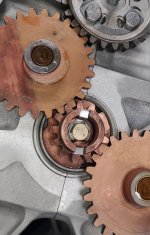
Given the distinctive shape, it was possible to identify it as a fragment from the crankshaft gear; fragment origin is outlined in red on the crankshaft gear below.
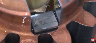
The borescope image of the crankshaft gear and the oil pump tabs is shown below. Note that the crankshaft bolt lockplate appears to be in the slot where the failure occurred.
Superior Air Parts sent a replacement crankshaft gear in return for the failed gear and metal fragment for metallurgical analysis. Superior concluded that the part was not defective, that it must have been overstressed. Given the location of the failure, it seems to have been stressed in the CCW direction (opposite the normal CW direction of the prop). As no prop strike and no backfire had occurred (to my knowledge), root cause was never determined. The new crankshaft gear was installed and the aircraft returned to service.
Second Crankshaft Gear Failure
During the March 2026 condition inspection at 383.6 hrs TT, the oil was changed and a nearly identical piece of metal was discovered in the oil screen:
Given that the small flake of the top of the gear teeth is slightly different, it is likely that this fragment is from the other side (180 degrees opposite) of the crankshaft gear (outlined in blue below):
It is also appears that the failure occurred in the CCW direction as before.
The borescope confirmed the piece came from the suspected place on the crankshaft gear and that as before it failed where the lockplate tab was inserted. The face of the fragment shows where it was pressured by the lockplate tab.
The oil had last been changed at 353.6 hrs TT; therefore the failure could have occurred at any time in preceding 30.0 hours. This means that the crankshaft gear installed in 2019 failed between 110 hrs and 140 hrs time-in-service. There were no prop strikes or backfires in this interval. No significant metal was observed in the oil filter, and the oil analysis was reported as 'normal'.
Superior has once again offered a replacement gear in return for the fractured part (in order to perform metallurgical analysis). I am reluctant to merely replace the gear again without establishing root cause (I have already dodged two bullets!).