Hi Guys,
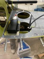
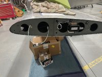
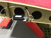
I have a GRT system and am at the point of deciding if I mount the magnometer in the tail or at the wingtip. It appears I will have less ferrous issues with the tail as the aileron counterbalances are in the vicinity. Also what do you use to mount as ferrous bolts aren't acceptable I assume. When running the wires to the magnometer, do they have to be a separate run, or can they be with other (lighting) wiring?
Thanks for the input!