Van's Air Force

The definitive Van's Aircraft support community! Buying, building or flying an RV? Join our exclusive family of mentors and enthusiasts!

G3X keeps red X'ing manifold pressure

agent4573

Well Known Member
I've been chasing this problem for over a year and have run out of ideas. At low MAP readings I keep losing manifold pressure gauge. It hasn't been critical yet since the SDS box has 2 independent MAP gauges I can reference to stay legal, but it is really annoying. It also came really close to having my wife's commercial check ride cancelled since the DPE saw it X out and tried to say the aircraft was unsafe to fly. It can happen anytime the MAP reading is below 15-16, but it increases in likelihood as it gets down to 10-11, normally during taxi or long descents, but also sometimes during pattern work. It has occasionally read 0 for a few seconds before it shows the X. As soon as throttle is increased it comes back to life.

Troubleshooting so far:
Replaced the sensor twice.
Replaced the line and adapter going to the engine to make sure it wasn't leaking.
Replaced the sensor side harness connector.
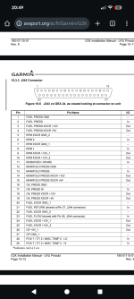
Repinned the 3 wires going into the GEA24.
Traced all ground wires during the last annual, didn't find anything loose. All my grounds go to a single point on the firewall, so ground loop issues shouldn't be a factor.

I would appreciate anything else I can check since MAP is one of the more important sensors and it would be nice if it worked consistently.
 
Gee whiz...that sounds like you've covered just about everything. Try calling the Garmin G3Xperts and see if they have any ideas. There could be some quirk with a software revision, or it won't work during a month with an "R" in it, or some other anomaly. The experts are pretty good about that kind of stuff.
 
Last edited:
This wont help solve the technical problem, but from a regulatory standpoint, if you’re flying in Day VFR, you can point any FAA guy (or Designee) to 91.205, where the opening sentence says “for aircraft with a Standard Airworthiness Certificate…..” Your RV has a “Special” AWC, so section 205 does not apply except as cited in your Ops Lims (in almost all cases, it applies for night or IFR Ops). You don;t need ANYTHING in the 205 list for Day VFR Ops.

Oh….many inspectors and designees don’t like to be proven wrong, so use this with discretion….
 
This wont help solve the technical problem, but from a regulatory standpoint, if you’re flying in Day VFR, you can point any FAA guy (or Designee) to 61.205, where the opening sentence says “for aircraft with a Standard Airworthiness Certificate…..” Your VR has a “Special” AWC, so section 205 does not apply except as cited in your Ops Lims (in almost all cases, it applies for night or IFR Ops). You don;t need ANYTHING in the 205 list for Day VFR Ops.

Oh….many inspectors and designees don’t like to be proven wrong, so use this with discretion….

A small point, but I think you meant 91.205, not 61.205.

--Ron
 
Assuming you have a Garmin GPT 30A or Kavlico sensor, these all work over a range of 0.5-4.5V. If you see a red-X or off-scale low indication, this makes me think "broken wire or loose connection", since an open circuit would produce a voltage outside the expected valid range of a working sensor.
 
There is the Vans supplied AN-NPT fitting with the built in snubber installed inline with the sensor on the "tree" mounted to the firewall.

Mburch, I agree. But I have verified no broken wires. I traced the wire run from the GEA24 to the firewall and then picked it up again firewall to sensor, the wire is not damaged. I replaced both ends of the wire as well with new connections and the problem persists.
 
Mburch, I agree. But I have verified no broken wires. I traced the wire run from the GEA24 to the firewall and then picked it up again firewall to sensor, the wire is not damaged. I replaced both ends of the wire as well with new connections and the problem persists.
The above implies an additional connection at the firewall?
 
I would bet $$$$ that your MAP sensor is positioned downhill from where the line connects to the manifold.

Reposition the sensor so that your MAP sensor is uphill from the connection.

I used a pair of adel clamps. One for the sensor and the other for attaching it to the engine frame. Garbage from the engine connection can kill the MAP sensor.
 
The above implies an additional connection at the firewall?
Negative. The solid length of wore goes through a passthrough that is filled with fire barrier. There is about 2 inches of cable that is not inspect-able, but I also don't see how the cable could get damaged since those 2 inches are completely retained from any movement.


You'll have to zoom in a little to see it, but the sensor is mounted as high as physically possible on the firewall behind the Raven air/oil separated. The line runs downhill from the sensor to the motor. I've checked that line multiple times for blockages and replaced it once. I've never found anything in it.
 

Attachments

  • PXL_20240317_212221192.jpg
    PXL_20240317_212221192.jpg
    2.3 MB · Views: 44
Assuming you have a Garmin GPT 30A or Kavlico sensor, these all work over a range of 0.5-4.5V. If you see a red-X or off-scale low indication, this makes me think "broken wire or loose connection", since an open circuit would produce a voltage outside the expected valid range of a working sensor.
Also, Some of these sensors are run off 5 volts and over time could create problems ifyou are pushing 12 volts to them. Garmin offers both, so might be worth while to confirm which power source you are using.
 
It's pinned to 12,13, and 15 in J243. Verified that today when I re-terminated the wiring.
 

Attachments

  • Screenshot_20251029-204920.png
    Screenshot_20251029-204920.png
    301 KB · Views: 15
What sleuthing have you done with a volt ohm meter? Do you have 5 volts at the sensor? Was the tracing of wires visual or did you check continuity? You’ve repinned and replaced sensor connectors. Could it be as simple as a bad crimp on the ground connector?
 
When you say, "At low MAP readings". It may be a clue. Is the restrictor fitting mounted directly to the engine? If you haven't already done it when you changed hoses, it may be worth pulling and verifying it isn't trying to plug off.
 
From a wiring perspective, but in a different type of machine, I had issue after issue and spent several thousand dollars on what turned out to be a bad ground wire that ohmmed OK but somehow would not function properly ??? Just a WAG...Good Luck, sounds like you've done all the hard work!
 
What sleuthing have you done with a volt ohm meter? Do you have 5 volts at the sensor? Was the tracing of wires visual or did you check continuity? You’ve repinned and replaced sensor connectors. Could it be as simple as a bad crimp on the ground connector?
I've traced them visually first to make sure there wasn't any damage. Then I got out the mutlimeter. 5 volts was verified at the sensor hot pin. Ground was verified during the troubleshooting and again when I repinned the GEA24 side connector yesterday. This sensor grounds back through the shielded cable and J243. I did verify the ground of the GEA24 during annual and couldn't find anything wrong. If it is a GEA24 ground issue, its odd that only this sensor is affected with a common LRU issue.

When you say, "At low MAP readings". It may be a clue. Is the restrictor fitting mounted directly to the engine? If you haven't already done it when you changed hoses, it may be worth pulling and verifying it isn't trying to plug off.

The restrictor is on the "tree" on the firewall. It's actually quite close to the sensor, which is the only thing I haven't changed in the system. Is there supposed to be a minimum distance between restrictor and sensor? If it is a physically anomaly based on restrictor replacement, it still strikes me as odd that the system would read 0. I haven't found a way to view the calibration curve when you select an existing sensor, so I'm not sure if the system is actually reading a pure vacuum or if it's displaying 0 even though it's still reading 6-10 inches.
 
Try putting in a potentiometer in place of the sensor and see if you can mimic the resistance of the sensor while the engine is off and on the ground and replicate the issue.

I don’t remember if the G3x has any range settings but if it does, have you checked them?
 
No range settings that I can find if you use a pre-programmed sensor. I might be able to set it up as a custom sensor and extend the lower voltage portion of the range. Ill get some pots ordered up, and do some ground testing.
 
The transducers are linear from .5 to 4.5v, so it should be easy to set it up on another input with custom settings, that way you could rule out a problem with the GEA or not.
 
I had problems with my MAP indications going red X from time to time.
In the hangar I removed the cowling and turned master switch to ON.
Then tapping the sensor and the connector with a screwdriver I found the problem to be related to vibrations / bad connection.
After removing the MAP FWF connector and soldered the wiering I have had no problems.

Good luck
 
My hangar mate had a similar issue with the oil temperature reading on his G3X. It would read perfectly on the ground and sometimes in flight. Then it would jump up into ridiculously high readings before coming back down. The readings were all over the place, which we knew was physically impossible. Often times, it would just red X out, then it would come back on again. All testing on the ground couldn't isolate or replicate the issue. Ultimately, we cut out the crimp splices between the oil temp sensor and the wires going to the Garmin box, then soldered the wire connections together. Problem solved.
 
Just to set the record straight, properly crimped connections, using the correct mil spec hardware and crimpers, are 100% reliable .
 
Last edited:
Just to set the record straight, properly crimped connections, using the correct mil spec hardware and crimpers, are 100% reliable .
Yup, I concur. My plane has many, many crimp connectors and they all work great. In the case of the one oil temp probe I referenced, there were thin wires that were in a spot that made it difficult to get the crimpers on juuust right to ensure a proper crimp. Or at least that's what we theorized.
 
I had problems with my MAP indications going red X from time to time.
In the hangar I removed the cowling and turned master switch to ON.
Then tapping the sensor and the connector with a screwdriver I found the problem to be related to vibrations / bad connection.
After removing the MAP FWF connector and soldered the wiering I have had no problems.

Good luck
I had the same intermittent problem. Ohm, voltage, continuity all good at the ends of the MAP three wire connector. Lightly jiggle, pulling on wire at connector would recreate the dropout. Eventually cut the wires & spliced in new connector pigtail assembly ... voila
 
There is the Vans supplied AN-NPT fitting with the built in snubber installed inline with the sensor on the "tree" mounted to the firewall.

Mburch, I agree. But I have verified no broken wires. I traced the wire run from the GEA24 to the firewall and then picked it up again firewall to sensor, the wire is not damaged. I replaced both ends of the wire as well with new connections and the problem persists.
Still, don’t discount the actual wires themselves. Years ago, I had similar trouble with a hall effect rpm sensor on the mag feeding my VM1000C.

I went almost two years troubleshooting like you did. The multimeter became an appendage. I replaced sensors three times, connectors multiple times, checked harness with wiggle test multiple times, replaced the display with an extra, and even swapped out the mag. I finally decided that the only thing I hadn’t replaced were the wires themselves. I made a new harness and the problem was solved. I still couldn’t find or explain the problem even when I pulled out the old harness and inspected it. Drove me nuts for two years!
 
Last edited:
Back
Top