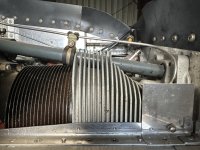
Interesting thoughts here. I don't believe that excess flow from the lifter bore clearance flows to the rocker box. Yes, there is high pressure oil flowing to each lifter bore and clearances can be 3-4 thou. However, IIRC, that area has drains cast into the case to allow the excess flow to drain back to the sump. There would be a great deal of excess flow from that big of a clearance and that require drains. There is an area below the tube exit to collect this oil for the drain. It would be poor engineering if you allowed all that flow to go to the rocker box. Any blockage or leakage in that return sysem would quickly lead to serious issues. So, I don't believe that is a variable in this equation.
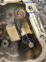
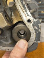
However, there is a clearance in the plunger assembly. There is a piston that goes into the body of the plunger. It is about a 1 thou clearance, maybe less. IIRC, these are all hand lapped for a very close slip fit. Oil flows into the case lifter bore and enters the lifter via a hole in it. That floods the lifter cavity. That oil then flows into the plunger assy via its bottom tube and past the check ball. The pressurized oil now in the plunger cylinder pushes up on the piston and removes any valve lash. There is also a clearance between the plunger body and the lifter bore. oil below the plunger is pressurized, so there will be some leakage via that clearance, but it is also slip fit and nowhere near .004'
While everyone else uses a bypass channel in the plunger assy to move some of the oil off to the pushrod, lyc only uses bleed past this plunger piston slip fit and past the plunger assy clearance to feed the pushrod. Therefore, tolerance differences will result in different flow rates. Then there is the plunger lifter bore clearance. Any oil bleeding past this area will also flow to the pushrod, as it is under the lifter cap riding in the lifter bore. Any leakage past the cap should flow back to the case drain, though a bit could be lung into the tube.
So, two clearance variables that will influence flow rate to the rocker box. Neither of those two interfaces really move much, so they don't wear.


")


 For my next attempt, I am going to add ceaser salad dressing to my oil and observe the effect on sticking valves; In tribute to Mike busch, I will also force my cylinders to 300 and note the relationship, with and without the dressing.