RV8Squaz
Well Known Member
Hello braintrust,
I performed an induction leak test per Mike Busch's article (excerpt attached below). In his article, he states, "If one cylinder (or two adjacent cylinders) exhibit(s) significantly less change than the others, suspect an induction system leak affecting that cylinder (or those adjacent cylinders)." The problem is that he doesn't quantify "significantly less change."
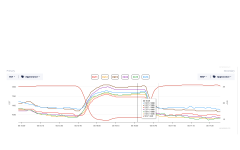
Here's a screen grab from the my test. I'll save you the simple math. The change for each cylinder 1, 2, 3, 4, 5, and 6 is 90, 120, 120, 140, 130, and 85. This is fairly consistent at various time points. I'm not sure there is anything significant here. The odd thing is that the EGT's go up when manifold pressure is reduced from 25 to 15. I performed the test exactly as written in the article. The engine is a Lyc. AEIO-540-L1B5. It's been modified with 10:1 pistons and a 6 into 1 Skydynamics exhaust.
Thanks!
I performed an induction leak test per Mike Busch's article (excerpt attached below). In his article, he states, "If one cylinder (or two adjacent cylinders) exhibit(s) significantly less change than the others, suspect an induction system leak affecting that cylinder (or those adjacent cylinders)." The problem is that he doesn't quantify "significantly less change."
Here's a screen grab from the my test. I'll save you the simple math. The change for each cylinder 1, 2, 3, 4, 5, and 6 is 90, 120, 120, 140, 130, and 85. This is fairly consistent at various time points. I'm not sure there is anything significant here. The odd thing is that the EGT's go up when manifold pressure is reduced from 25 to 15. I performed the test exactly as written in the article. The engine is a Lyc. AEIO-540-L1B5. It's been modified with 10:1 pistons and a 6 into 1 Skydynamics exhaust.
Thanks!