
Van's Air Force
You are using an out of date browser. It may not display this or other websites correctly.
You should upgrade or use an alternative browser.
You should upgrade or use an alternative browser.
High oil temp on relatively new engine
- Thread starter Bavafa
- Start date

I knew you would pick up on that. Sorry I made a mistake. Actually 0.4755097 gallons per minute for all four nozzles. About......... Still, it's a lot of oil and the oil pump has to be in good shape and be able to keep up with the flow or the oil pressure will drop. The cooling nozzles start to flow at about 40 lbs. of oil pressure so it shouldn't affect the idle oil pressure.450 ml per nozzle x four nozzles = 1.9 quarts. Interesting data bit!
Yes.Have you verified that the EIS is configured for the correct temperature sensor?
It is generally the style that makes the efficiency difference. Bar & plate vs drawn cup. Not surprisingly, the less efficient one is cheaper to make, so more common. The coolers from reputable firms have data sheets that provide heat transfer rate for different airflows. That data would be a better benchmark for specifying coolers.I think we are doing ourselves a disservice when we spec an oil cooler based upon "row count" and very little else -- Not all 6/7 (or 9 or 11 or 13) are the same in efficiency.
For grins and giggles - here're some pictures of identically sized units ; Which one do you think would cool more effectively? (answer below)...
View attachment 88481
View attachment 88482
No surprise - the unit in the last picture "cools" more effectively - with one less "row". It cools an IO-360-A1B6D w/piston squirters, operating in a ~144Ktas airframe...
I don't ever recall seeing a side by side comparison of heat exchangers from the various suppliers: Southwind/Stewart-Warner/Meggitt et al, AirFlow, Niagara-NDM, Aeroclassics, Mishimoto, Sertrab... Maybe I missed it..
Last edited:
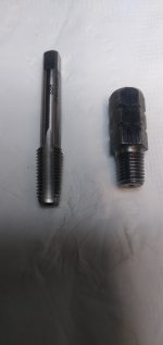
Which engine are these nozzles in? The factory-built 390's have larger nozzles than the 360's. DanH's 390 was an early one built by Barrett, so it most likely has the smaller nozzles.One piston cooling nozzles on my engine flow about 450 ml of 185 degree f, 20/50 weight oil at 70 lbs. of oil pressure in one minute. That's four quarts per minute. All most a gallon per minute just for the oil cooling nozzles.
These are the older 390 nozzles.Which engine are these nozzles in? The factory-built 390's have larger nozzles than the 360's. DanH's 390 was an early one built by Barrett, so it most likely has the smaller nozzles.

The coolers from reputable firms have data sheets that provide heat transfer rate for different airflows. That data would be a better benchmark for specifying coolers.
Yes. Harder to find and compare than it should be. Different units, air/oil flow rates etc.
this is my best stab at it from a few years ago. Adding SW coolers into the chart.
...and here are the SW charts...View attachment 88507
Yes. Harder to find and compare than it should be. Different units, air/oil flow rates etc.
this is my best stab at it from a few years ago. Adding SW coolers into the chart.
Which engine are these nozzles in? The factory-built 390's have larger nozzles than the 360's. DanH's 390 was an early one built by Barrett, so it most likely has the smaller nozzles.
Interesting question. I have no idea which nozzles are in my kit 390. Although small main, it was 390 case, not a modified 360 case. Are the flow rates for the two nozzles in a publication somewhere ?
Have not seen the flow specs published. And if we called Lycoming, we'd probably not get an answer (unless a guy like @Ironflight knew specifically whom to talk to). We know the part numbers so one of us could buy one of each and flow-test ourselves... actually maybe Steve Korney might do it since he has the setup...Interesting question. I have no idea which nozzles are in my kit 390. Although small main, it was 390 case, not a modified 360 case. Are the flow rates for the two nozzles in a publication somewhere ?
YIO-390-B, IO-390-C, AEIO-390-A, IO-390-D, IO-580-B1A:

TIO-540, IO-360-A, and all other 360/540's that I could find:
And here's something I've never seen before; the nozzle can be disassembled, at least with the version in the IGO-540:


The reply I got from Rhonda Barrett when I asked about the two different nozzles:

Of course this is all a bit esoteric and you'd need a cylinder like Paul D got with his Rocket project with the thermocouples embedded to be able to measure the temp delta in the piston crown (and/or CHT & oil temp deltas).
Last edited:
I just pulled jugs on a 360 PV engine and removed the squirters while in there. They were 1/16” npt, not 1/8”Have not seen the flow specs published. And if we called Lycoming, we'd probably not get an answer (unless a guy like @Ironflight knew specifically whom to talk to). We know the part numbers so one of us could buy one of each and flow-test ourselves... actually maybe Steve Korney might do it since he has the setup...
YIO-390-B, IO-390-C, AEIO-390-A, IO-390-D, IO-580-B1A:
View attachment 88538
TIO-540, IO-360-A, and all other 360/540's that I could find:
View attachment 88539
The plug used without nozzles on 360's (and probably the 390's have the same dia):
View attachment 88540
And here's something I've never seen before; the nozzle can be disassembled, at least with the version in the IGO-540:
View attachment 88541View attachment 88542
The reply I got from Rhonda Barrett when I asked about the two different nozzles:
View attachment 88543
Of course this is all a bit esoteric and you'd need a cylinder like Paul D got with his Rocket project with the thermocouples embedded to be able to measure the temp delta in the piston crown (and/or CHT & oil temp deltas).
Interesting! Then that parts catalog is wrong. I thought 1/8" sounded big. Edited my post above.My piston cooling nozzles are 1/16 - 27 NPT and the hole is 0.050 in diameter. I think it's the old style if the newer ones have a 1/8 NPT. That is the one measured the flow on.
Hey Dan. Can you calculate the Viscosity of the oil from the orifice size and pressure?My piston cooling nozzles are 1/16 - 27 NPT and the hole is 0.050 in diameter. I think it's the old style if the newer ones have a 1/8 NPT. That is the one measured the flow on.
Hey Dan. Can you calculate the Viscosity of the oil from the orifice size and pressure?
Not without some study.
Just to circle back on this issue, I got a chance to take a look and help my friend. What I found, I believe multiple issues that were a contributing factor but perhaps the biggest and main one was wrong timing. The PMAGS were timed proximately 5 degree before TDC (advanced) and there were multiple baffling mishaps that were relatively big hole including missing the foam that blocks air from exiting top cowl right above prop governor. After making some of these changes/fixes, we did a short flight and the oil temp was very normal for a RV14A. With the OAT reporting in the 90s, two people and full fuel the oil temp was in the 197-198 range.
Thanks for all who chimed in here
Thanks for all who chimed in here
Reminder, typically pMag timing is set with the crank at 5 degrees after TDC for angle head engines. This yields a pMag timing setting of 20 degrees before TDC.Just to circle back on this issue, I got a chance to take a look and help my friend. What I found, I believe multiple issues that were a contributing factor but perhaps the biggest and main one was wrong timing. The PMAGS were timed proximately 5 degree before TDC (advanced) and there were multiple baffling mishaps that were relatively big hole including missing the foam that blocks air from exiting top cowl right above prop governor. After making some of these changes/fixes, we did a short flight and the oil temp was very normal for a RV14A. With the OAT reporting in the 90s, two people and full fuel the oil temp was in the 197-198 range.
Thanks for all who chimed in here
Also I suggest you verify the pMag timing jumper is installed.
Carl
Yes, I did not provide all the steps and troubleshooting I have done but the fix. We did confirm the oil sensor was reading and reporting accurately.i do not know much about this but wouldn't doing the easiest, cheapest thing first be an idea, change the oil temp sensor?
Verified, it was installed and its integrity was checked. I have troubleshot others that had the jumper installed but one leg broken and had the appearance of having the jumper in place.Reminder, typically pMag timing is set with the crank at 5 degrees after TDC for angle head engines. This yields a pMag timing setting of 20 degrees before TDC.
Also I suggest you verify the pMag timing jumper is installed.
Carl
Verified, it was installed and its integrity was checked. I have troubleshot others that had the jumper installed but one leg broken and had the appearance of having the jumper in place.
I'll thread drift on this.... one of the things I'd like changed the most on the PMAG is the connector. It would be so much better if it had a very well connected wire bundle out to a DB9 or similar where the pins could be securely fastened and not subject to vibration-related problems. I have had the RPM all over the place - PMAG wire. I've had a PMAG not want to start up - PMAG wire. I've had a couple of other things.... PMAG wire!
Carefully routing the wires through the strain relief and doing all I can - PMAG wire! It just has to be checked all the time.
I am sure now that Harzel has bought them out, they will fix thisI'll thread drift on this.... one of the things I'd like changed the most on the PMAG is the connector. It would be so much better if it had a very well connected wire bundle out to a DB9 or similar where the pins could be securely fastened and not subject to vibration-related problems. I have had the RPM all over the place - PMAG wire. I've had a PMAG not want to start up - PMAG wire. I've had a couple of other things.... PMAG wire!
Carefully routing the wires through the strain relief and doing all I can - PMAG wire! It just has to be checked all the time.
")
Personally I have never had any issues with the connector or the wire but short of anything bulky connector like a DB9 would be great
Personally I have never had any issues with the connector or the wire but short of anything bulky connector like a DB9 would be great
Bulky indeed. A DB9 would be a d-subminiature type ("D") with a 25 pin body ("B"), but only 9 installed pins. What you want is a DE9. Just polishing the pins, old bean....
Dan, you are correct and an expert in many things, and while you are perhaps technically correct a search on Mouser for "db9" returns 1195 items, a lot of them cable assemblies with DE9 attached. There are tech specs, and then there are common terms..... DE9 refers specifically to the 9 pin connector itself.
Aircraft Spruce calls it a DB9 too: https://www.aircraftspruce.com/catalog/elpages/pinconnector11-12149.php?clickkey=53635
It's all copacetic.....
Aircraft Spruce calls it a DB9 too: https://www.aircraftspruce.com/catalog/elpages/pinconnector11-12149.php?clickkey=53635
It's all copacetic.....
I am sure you well know that on a 390 engine, there isn't a full 360 range that the PMAG can be installed. With a DB or DE type connector if the shell is installed, it will make it rather cumbersome. Without the shell, I am not sure if that would be any improvement. The engine that I was just helping to troubleshoot, had so many parts and some of them with less planning ahead that made any access even to the oil filter rather difficult.Bulky indeed. A DB9 would be a d-subminiature type ("D") with a 25 pin body ("B"), but only 9 installed pins. What you want is a DE9. Just polishing the pins, old bean....
However, there is always room for improvement on any products and any of these connectors can be installed and be relatively safe with a bit of care.
There are tech specs, and then there are common terms....
Very true. My mentor was militant about using correct terms, and it kind a rubbed off. As noted, here it's just pin polishing.
FWIW, I'd spec a pigtail running through a factory installed Adel or similar fixation, then terminate with something like an Amphenol AT or Deutsch DT.
Aircraft Spruce calls it a DB9 too: https://www.aircraftspruce.com/catalog/elpages/pinconnector11-12149.php?clickkey=53635
Seriously, builders are well advised to be cautious about what the Spruce catalog writers call anything.
Last edited:
[email protected]
Member
Not if it is not defective or some how clogged. I have the same cooler in my existing and last RV and did not have any issues like this.
[email protected]
Member
I have the same setup including oil cooler, 5” scat, and now with the warmer days my oil temperature are moderately high. Today saw 223°F after completing a climb to 8000’ with an OAT of 71°F. I live in Colorado in the thinner air. After getting into cruise at 65% power, the OT dropped down to only 221°F.This is a RV14A with a IO390-EXP119 engine and all is setup based on standard installation which uses Airflow performance oil cooler with a 5" scat tubing. I have not seen the CHT but all indication is that it is normal temp. This engine has piston squirters and those are standard on this engine and the oil cooler is a 13 row but the temp is not normal based on my experience. There is very little verified info about the past behavior/temp of the engine as the 40 hours fly offs was done by another pilot and he has provided little info other than 'all was normal'
I’m looking for ideas in addition to:
1) removing the tunnel cowl flap to increase exit air.
2) cut a hole in the bottom cowl to increase exit air
3) insert Antisplat electric cowl flap on the bottom of the lower cowl.
Engine has 60 hours, oil consumption is nominal, CHTs about 360°F.
Any other suggestions?
I would need to know more info, for instance at what rate were you climbing and from what elevation to 8K. But as the minimum I would recommend against any changes that it is harder to undo such as your #2 and #3 ideas. Increasing exit air will help with cooling but it comes as a cost of drag, there are probably thousands of RV14 (I don't know how many exactly) and few of them have gone that route.I have the same setup including oil cooler, 5” scat, and now with the warmer days my oil temperature are moderately high. Today saw 223°F after completing a climb to 8000’ with an OAT of 71°F. I live in Colorado in the thinner air. After getting into cruise at 65% power, the OT dropped down to only 221°F.
I’m looking for ideas in addition to:
1) removing the tunnel cowl flap to increase exit air.
2) cut a hole in the bottom cowl to increase exit air
3) insert Antisplat electric cowl flap on the bottom of the lower cowl.
Engine has 60 hours, oil consumption is nominal, CHTs about 360°F.
Any other suggestions?
[email protected]
Member
The climb to 8000’ was very gradual at around 120 knots or about 500 fpm. The flight was from 5100’ to 7000’ with OT around 215°F. Did a couple of practice approaches down to about 5600’ then a slow climb up to the 8000’. It was during this climb the OT increased to 223°F. It was also a reduced power climb at about 60% power.I would need to know more info, for instance at what rate were you climbing and from what elevation to 8K. But as the minimum I would recommend against any changes that it is harder to undo such as your #2 and #3 ideas. Increasing exit air will help with cooling but it comes as a cost of drag, there are probably thousands of RV14 (I don't know how many exactly) and few of them have gone that route.
Today saw 223°F after completing a climb to 8000’ with an OAT of 71°F. I live in Colorado in the thinner air. After getting into cruise at 65% power, the OT dropped down to only 221°F.
Review Mehrdad's post, #66. Dead on. The majority of cooling complaints are due to poor baffles and seals, and/or advanced timing.
You appear to be running an EFII system, which means adjustable, variable timing. For a 390 on variable timing, set 20 BTDC as base timing, with max advance no more than 28 or so. Even 28 nets almost nothing unless you're cruising very lean.
Did a couple of practice approaches down to about 5600’ then a slow climb up to the 8000’. It was during this climb the OT increased to 223°F. It was also a reduced power climb at about 60% power.
Note a manifold pressure reduction with such a system = more advance.
[email protected]
Member
Dan,Review Mehrdad's post, #66. Dead on. The majority of cooling complaints are due to poor baffles and seals, and/or advanced timing.
You appear to be running an EFII system, which means adjustable, variable timing. For a 390 on variable timing, set 20 BTDC as base timing, with max advance no more than 28 or so. Even 28 nets almost nothing unless you're cruising very lean.
Note a manifold pressure reduction with such a system = more advance.
You are correct in my engine having the EFII system (good sleuthing!). I have had several eyes on baffling and intake foam and it’s all secure and well sealed.
The EFII system does produce ten to fifteen percent more horsepower which I believe is contributing to higher temperatures. I’ll have to look into more the changing of the base timing.
There are OK baffling, good baffling and excellent baffling, if you can search for old posts from Dan, you will find some good example of excellent baffling which helps much with this. Checking or having ability to change your advance timing will help very much with this engine. In regards the more perceived/produced power of EFII , noteworthy that your temps are not for the high power operation.Dan,
You are correct in my engine having the EFII system (good sleuthing!). I have had several eyes on baffling and intake foam and it’s all secure and well sealed.
The EFII system does produce ten to fifteen percent more horsepower which I believe is contributing to higher temperatures. I’ll have to look into more the changing of the base timing.
The EFII system does produce ten to fifteen percent more horsepower which I believe is contributing to higher temperatures.

My 390 early Thunderbolt model with a 4 in. SCEET 210 HP (RV-14A) OT's almost identical no matter if I'm 20", 22" or 24" / 2,400 RPM and 120 knots with EFII-32 so I normally use 24 sq to get to cooler temps faster. If it's the first flight of the day typically get to 205F and if the engine is already heat soaked gets to 215F. This is in Florida summers. Standard EFII advance map. Once in cruise at altitude (5,500 to 8,500) OT settles down to the 195 F range. LOP normally knocks another 5 - 7 degrees OT reduction. Savvy OT analysis says I'm in the 50 percentile for OT in cruise. Data all summer ops in Florida. Ohio ops in summer obviously slightly lower OT's. 650 hrs.Note a manifold pressure reduction with such a system = more advance.
Last edited:
Oil coolers work with air flow through them. High pressure on top and low pressure on the bottom. Oil cooler manufacturers use 5 inches of pressure diffrential between top and bottom. If you measure what you have, then you will know the problem.My 390 early Thunderbolt model with a 4 in. SCEET 210 HP (RV-14A) OT's almost identical no matter if I'm 20", 22" or 24" / 2,400 RPM and 120 knots with EFII-32 so I normally use 24 sq to get to cooler temps faster. If it's the first flight of the day typically get to 205F and if the engine is already heat soaked gets to 215F. This is in Florida summers. Standard EFII advance map. Once in cruise at altitude (5,500 to 8,500) OT settles down to the 195 F range. LOP normally knocks another 5 - 7 degrees OT reduction. Savvey OT analysis says I'm in the 50 percentile for OT in cruise. Data all summer ops in Florida. Ohio ops in summer obviously slightly lower OT's. 650 hrs.
Oil coolers work with air flow through them. If you measure what you have, then you will know the problem.
Thanks, was not sure about that.
 Didn't realize I had an issue, Savvy doesn't think so compared to over 200 390's they are logging.
I know you and others who have responded to the supposably increased HP rating of EFI systems, but do you have any data to support this concern? I get it 10 - 15% is probably a stretch and not sure where that data comes from but more important what does the ability to match flow each injector fuel input at exactly the optimum time a cylinder needs fuel vs dribbling fuel constantly to a cylinder provide? (High tech spider technology) I don't have the data but do you or anyone else? I’m not trying to cause a controversy or dispute but does anyone have data to support or refute this claim? I do know when I operate LOP, I am able to easily get a 35% increase in efficiency measured by MPG. Maybe that's normal for LOP operations. I am interested in the data. Thanks
Last edited:
“Dribbling” fuel into the intake has been done for decades in the auto world. Some have moved to sequential injection, but not that many. Lots of science to say that timing the injection to the valve opening provides very little gain. If this improved hp it would also improve milege and auto makers are fanatics about mpg. The factt that most haven’t all moved to it should tell you something. Further, there is a LOT of engineering involved in the timing to get any gains and i can all but assure you their one man shop didn’t do it. Even greater, he is not even doing sequential injection. In order to do sequential injection, you need a cam position sensor and there is no way to implement that on a lyc. Efii only sees the crank position and therefore he is shhoting fuel at a closed valve half the time, just like everyone else.View attachment 90197
I know you and others who have responded to the supposably increased HP rating of EFI systems, but do you have any data to support this concern? I get it 10 - 15% is probably a stretch and not sure where that data comes from but more important what does the ability to match flow each injector fuel input at exactly the optimum time a cylinder needs fuel vs dribbling fuel constantly to a cylinder provide? (High tech spider technology) I don't have the data but do you or anyone else? I’m not trying to cause a controversy or dispute but does anyone have data to support or refute this claim? I do know when I operate LOP, I am able to easily get a 35% increase in efficiency measured by MPG. Maybe that's normal for LOP operations. I am interested in data not graphical comics. Thanks
Sorry, but there is nothing that efii is doing over fuel servos and electronic ignition that justifies a power increase. Saying it makes more power sells stuff, so they say it. Just sleezy marketing. Notice that ross at sds selling the same thing makes no such claims? Responsible marketing.
Last edited:
Thanks for the data........I need to ask my son (Honda Engineering - Ohio Boiler grad) how to perform the cup flow dribble test on my Acura it seems....“Dribbling” fuel into the intake has been done for decades in the auto world. Some have moved to sequential injection, but not that many.
")
Auto fuel injectors don't dribble fuel; I was just quoting your terminology. They inject it forcefully at around 40PSI through a small orifice and it is very finely atomized (an advantage over or crude mech injection). They have improved injector designs to create smaller and smaller droplets, as this improves fuel efficiency at least marginally. The injector opening time is precisely controlled (down to fractions of a ms) to meter fuel volume injected for the conditions at the moment and the fuel tends to stay in that atomized state while waiting for the valve to open. testing is difficult, as you have to account for the ramp up/down periods (where flow transition from none to full) of the injector opening and closing. This is precise enough that the ECU compensates time for battery voltage. This creates a larger impact on shorter open times than longer. All the math is in the ECU.Thanks for the data........I need to ask my son (Honda Engineering - Ohio Boiler grad) how to perform the cup flow dribble test on my Acura it seems....
AZSteve053
Well Known Member
Just a thought from left field - Do an OIL & FILTER change using a good summer weight (W100) and send a sample out for analysis which shows actual condition of removed oil & don't forget to cut the filter looking for FOD or blockage.
Standard EFII advance map.
Which is?
...do you have any data...?
Yes.

I get it 10 - 15% is probably a stretch and not sure where that data comes from
Switching from an updraft carb to any of the better flowing horizontal intakes would improve power, but that's a configuration change. The updraft plumbing is pretty awful.
Same intake configuration, Bendix style vs PWM? No significant difference at WOT.
but more important what does the ability to match flow each injector fuel input at exactly the optimum time a cylinder needs fuel vs dribbling fuel constantly to a cylinder provide?
Both mechanical injection and your EFII system deliver fuel through all 720 degrees of the cycle.
Bendix nozzle pressure is well below 1 psi at idle, so "dribbling" is an accurate description there. Pressure remains low up through the economy range. For example, with 0.028" restrictors, 6 GPH is only a little over 1 psi. The delivery is not quite a dribble, but it is quite blobby.
Pressure rises to roughly 8.5 psi for the 105 lbs/hr minimum flow for rated power for a 210 hp 390. Typical for a -119 with an FM-200 would be closer to 10 psi nozzle pressure at WOT. The delivery is an aerated stream about the size of a mechanical pencil lead...no dribble.
When the intake valve opens, fuel delivered by nozzle or PWM injector flashes to vapor due to manifold heat and pressure drop...straight physics. The pressure drop varies with throttle setting, so flash vaporization works very well at WOT. However, it's not so great at idle. It needs the drop to break up the blobs.
A PWM injector is suppled with a constant higher supply pressure, roughly 35 to 45 psi. And it's the same at any RPM, so idle fuel is sprayed, not blobbed. Atomization is much better at idle and into the low power cruise range, and highly atomized fuel is more easily flashed to vapor. As a result, there is less cycle-to-cycle combustion variation. Idle is smoother, and it's possible to run much further LOP, if the speed loss is acceptable. This is the primary advantage of EFI in our application.
I do know when I operate LOP, I am able to easily get a 35% increase in efficiency measured by MPG. I am interested in the data.
Data from the dyno at Barrett. Back to back runs with Monty at the controls, same day, same engine, about 11 years ago. Raw data, and standard correction factors.
The first three are simple power runs. The first is 2700 rpm, adjusting mixture for maximum dynamometer torque. Next was a reduction to 24 inches and
2700 to simulate WOT climb through roughly 5000 feet, again adjusting mixture for max torque. The third was 19.5 inches/2700 to simulate 10,000 ft, same thing.
The fourth and fifth tests were subjective, based on operator observation. We set 24 inches/2400 and 19.5 inches/2400 to simulate cruise conditions, then searched for the lowest possible fuel flow without significant torque loss…the LOP drop observed on standard mixture vs torque charts. Being subjective, these values are not absolutes.
The sixth run for the EFII system followed a timing change, in an attempt to increase max power.
Let's remember the point here. It isn't about which system posted the best numbers. It's about neither posting any significant advantage in the best power realm.

Last edited:
Thanks !! and now we have the data !! I'll post my ignition map when I get to my hangar. Running LOP sure seems to be able to push it a long way before engine even begins to run rough. I found running -28 to 30% LOP pretty well in the sweat spot for power and efficiency.Which is?
Yes.
View attachment 90219
Switching from an updraft carb to any of the better flowing horizontal intakes would improve power, but that's a configuration change. The updraft plumbing is pretty awful.
Same intake configuration, Bendix style vs PWM? No significant difference at WOT.
Both mechanical injection and your EFII system deliver fuel through all 720 degrees of the cycle.
Bendix nozzle pressure is well below 1 psi at idle, so "dribbling" is an accurate description there. Pressure remains low up through the economy range. For example, with 0.028" restrictors, 6 GPH is only a little over 1 psi. The delivery is not quite a dribble, but it is quite blobby.
Pressure rises to roughly 8.5 psi for the 105 lbs/hr minimum flow for rated power for a 210 hp 390. Typical for a -119 with an FM-200 would be closer to 10 psi nozzle pressure at WOT. The delivery is an aerated stream about the size of a mechanical pencil lead...no dribble.
When the intake valve opens, fuel delivered by nozzle or PWM injector flashes to vapor due to manifold heat and pressure drop...straight physics. The pressure drop varies with throttle setting, so flash vaporization works very well at WOT. However, it's not so great at idle. It needs the drop to break up the blobs.
A PWM injector is suppled with a constant higher supply pressure, roughly 35 to 45 psi. And it's the same at any RPM, so idle fuel is sprayed, not blobbed. Atomization is much better at idle and into the low power cruise range, and highly atomized fuel is more easily flashed to vapor. As a result, there is less cycle-to-cycle combustion variation. Idle is smoother, and it's possible to run much further LOP, if the speed loss is acceptable. This is the primary advantage of EFI in our application.
Data from the dyno at Barrett. Back to back runs with Monty at the controls, same day, same engine, about 11 years ago. Raw data, and standard correction factors.
The first three are simple power runs. The first is 2700 rpm, adjusting mixture for maximum dynamometer torque. Next was a reduction to 24 inches and
2700 to simulate WOT climb through roughly 5000 feet, again adjusting mixture for max torque. The third was 19.5 inches/2700 to simulate 10,000 ft, same thing.
The fourth and fifth tests were subjective, based on operator observation. We set 24 inches/2400 and 19.5 inches/2400 to simulate cruise conditions, then searched for the lowest possible fuel flow without significant torque loss…the LOP drop observed on standard mixture vs torque charts. Being subjective, these values are not absolutes.
The sixth run for the EFII system followed a timing change, in an attempt to increase max power.
Let's remember the point here. It isn't about which system posted the best numbers. It's about neither posting any significant advantage in the best power realm.
View attachment 90220
And thanks again for the data !
At what altitude can you run LOP with that percentage? I was able to go LOP about 80F with my standard 390 up to 12-13K elevation and as I went higher this would reduced till I changed my nuzzles to .024 which helped a great deal up to 17k. With my FM200 (EXP119) this is not as much and even though I have gone down to .0255, at about 15k I get only about 15-25F LOP. The fuel burn is still pretty good, about 8G at 162k. I understand if I change my fuel pump to a higher pressure than I could go to a smaller nuzzle but at this point I am satisfied with the setup.Thanks !! and now we have the data !! I'll post my ignition map when I get to my hangar. Running LOP sure seems to be able to push it a long way before engine even begins to run rough. I found running -28 to 30% LOP pretty well in the sweat spot for power and efficiency.
And thanks again for the data !
Are you saying you got 276 horse power from a io-390 at WOT, Std Day, Sea level? What was the fuel flow for that HP.?Which is?
Yes.
View attachment 90219
Switching from an updraft carb to any of the better flowing horizontal intakes would improve power, but that's a configuration change. The updraft plumbing is pretty awful.
Same intake configuration, Bendix style vs PWM? No significant difference at WOT.
Both mechanical injection and your EFII system deliver fuel through all 720 degrees of the cycle.
Bendix nozzle pressure is well below 1 psi at idle, so "dribbling" is an accurate description there. Pressure remains low up through the economy range. For example, with 0.028" restrictors, 6 GPH is only a little over 1 psi. The delivery is not quite a dribble, but it is quite blobby.
Pressure rises to roughly 8.5 psi for the 105 lbs/hr minimum flow for rated power for a 210 hp 390. Typical for a -119 with an FM-200 would be closer to 10 psi nozzle pressure at WOT. The delivery is an aerated stream about the size of a mechanical pencil lead...no dribble.
When the intake valve opens, fuel delivered by nozzle or PWM injector flashes to vapor due to manifold heat and pressure drop...straight physics. The pressure drop varies with throttle setting, so flash vaporization works very well at WOT. However, it's not so great at idle. It needs the drop to break up the blobs.
A PWM injector is suppled with a constant higher supply pressure, roughly 35 to 45 psi. And it's the same at any RPM, so idle fuel is sprayed, not blobbed. Atomization is much better at idle and into the low power cruise range, and highly atomized fuel is more easily flashed to vapor. As a result, there is less cycle-to-cycle combustion variation. Idle is smoother, and it's possible to run much further LOP, if the speed loss is acceptable. This is the primary advantage of EFI in our application.
Data from the dyno at Barrett. Back to back runs with Monty at the controls, same day, same engine, about 11 years ago. Raw data, and standard correction factors.
The first three are simple power runs. The first is 2700 rpm, adjusting mixture for maximum dynamometer torque. Next was a reduction to 24 inches and
2700 to simulate WOT climb through roughly 5000 feet, again adjusting mixture for max torque. The third was 19.5 inches/2700 to simulate 10,000 ft, same thing.
The fourth and fifth tests were subjective, based on operator observation. We set 24 inches/2400 and 19.5 inches/2400 to simulate cruise conditions, then searched for the lowest possible fuel flow without significant torque loss…the LOP drop observed on standard mixture vs torque charts. Being subjective, these values are not absolutes.
The sixth run for the EFII system followed a timing change, in an attempt to increase max power.
Let's remember the point here. It isn't about which system posted the best numbers. It's about neither posting any significant advantage in the best power realm.
View attachment 90220
Are you saying you got 276 horse power from a io-390 at WOT, Std Day, Sea level? What was the fuel flow for that HP.?
No. The dataset is from an IO 540.
Got it. ThanksNo. The dataset is from an IO 540.
