Van's Air Force

The definitive Van's Aircraft support community! Buying, building or flying an RV? Join our exclusive family of mentors and enthusiasts!

RV-8 electrical system critique

Ben Ellis

Well Known Member
Sponsor
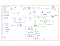
I’m getting ready to install the electrical system in my RV-8 and I was hoping you experienced builders could take a look at my power schematic and let me know if you see any issues. I based the design on Nuckoll’s Z-14. I fly IFR and wanted a dual isolated bus electrical system for several reasons. Each bus has its own battery and alternator/generator that runs all the time, and the devices are divided between the buses in a way that each bus has enough avionics to keep the plane right side up in the clouds and get me home.

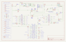
By design, the only way to connect the buses is with the cross feed contractor and that will remain open most of the time. The goal of isolation is why I don’t dual feed the Garmin avionics that allow it or automatically use both batteries to feed the starter. I can always close the cross feed contactor if needed. The only connection between the two buses when the cross feed contactor is open should be the voltage sense feed from bus 2 to the GEA 24 on bus 1, which is the only way I could figure out how to monitor the voltage of bus 2 through the G3X system.

I have an IO-390-EXP119 / Whirlwind 300-3B/A-72 up front so I’m putting one PC-680 in the rear for weight and balance and another in the floor of the forward baggage compartment for convenience and to shorten the big wire runs. Each battery contactor is near its battery, and the battery contactors feed to the cross feed contactor inside the right gear tower. The bus bars and fuse box are located close together in the right console area, a short run away from their power source at the cross feed contactor. I have a B&C forest of trees ground block that attaches to both sides of the firewall and all grounds will terminate here except for the few grounds indicated in the schematic as being local or engine grounds.

One question that comes to mind--will having the forward battery’s ground terminal connected to the firewall ground bus while the aft battery’s ground terminal is connected to the longeron create any noise or other problems?

Please let me know your thoughts and if you see any problems that I have missed.

Screenshot 2025-04-16 at 7.46.45 PM.png
 

Attachments

Last edited by a moderator:
A couple of thoughts:
- For most, starting a review using a block diagram is a major aid to help figure out what you are trying to achieve.
- Grounding the aft battery locally is not a problem, unless you are grounding avionics there as well as forward. Ground all avionics at your forest of tabs. Any such remote avionics should be connected with shielded wire. Use antioxidant on the battery ground wire to aluminum junction.
- Do you plan on engine start using both batteries in parallel? That is what I recommend.

Carl
 
Missing a wire from #1 batt switch (terminal 2) to batt contactor.
As drawn, all buses are tied together at top of dual bus feed box. No isolation.
Cross feed engaged light section of its switch misrouted.
 
Last edited:
Personally not a fan of dual buss architecture, added complexity and the small backup alt I don’t think is really suited to full time duty (that’s why it’s called a backup).
Electrically dependent engine is a different animal, not my cup of tea.
 
Is ground power needed with two on board batteries?
LEDs need a series resistor unless built in.
Cross feed engaged light should connect to switch terminal 5.
 
Nice diagram. I'd go with two small earthx batteries on the FW and carry a tool bag in the back for W&B - that's actually useful weight, unlike the battery and all the cabling to get the power to the panel and engine.
 
Thanks all for your comments. I corrected the errors that were pointed out.

If anyone sees any issues with my choice of wire and breaker sizes please let me know. One thing I'm unsure of is the feed for the Gerbing heated clothing controller. The controller says you should choose a fuse current rating based on the clothing you are hooking up. I don't know whether the intention is just to make sure you have enough room for the current draw, or if it's to limit fuse size to protect the wearer if the clothing starts pulling too much current.

I'm also unsure whether my fuse and wire sizes are right for the USB chargers and if wiring the two outlets in parallel on the same circuit is a good idea.

Personally not a fan of dual buss architecture, added complexity and the small backup alt I don’t think is really suited to full time duty (that’s why it’s called a backup).
Electrically dependent engine is a different animal, not my cup of tea.
I hear you about the dual bus, I know a lot of people don't see the need for it. The way I think about it is that if you replace the cross feed contactor with an avionics bus relay, switch the second battery to a smaller backup battery, and put the generator into backup mode then you would have a very common electrical system that people don't consider too complex even though it is basically the same setup. What I like about the dual bus setup, in addition to other benefits, is that I can crank the engine with the second battery, which you can't do with an avionics backup battery, while also having a battery that is cheaper and easier to replace in the field than a backup battery. Also, with my set up, if I ever have a contactor failure while away from home, I can still fly without having to find a replacement contactor or modify the electrical system. Some day I may switch to fully electronic ignition and FI and with this architecture I wouldn't really need to modify many things to do that. I already plumbed the fuel tanks for return lines...

As for the Monkworkz, apparently it's running on a number of planes as the only power generator and I don't think the designer claims it's just a backup power source. I'll report back in a few years to let everyone know how it goes. I like it's many advantages over a more traditional backup alternator.

Is ground power needed with two on board batteries?
Definitely not needed... but I put it there for ground power during avionics installation and testing, database updates, hangar flying, etc. I never want to have to worry about me or someone else hooking up battery leads backwards or pumping too many volts into the bus and frying $40k in avionics. It's a small trade off in time, money and weight for peace of mind and convenience.

LEDs need a series resistor unless built in.
Good catch. I plan to use one of these: https://www.steinair.com/product/red-led-indicator-light-12v/. I couldn't think of a good way to draw an appropriate symbol so just used what KiCad had built in.

I'd go with two small earthx batteries on the FW and carry a tool bag in the back for W&B - that's actually useful weight, unlike the battery and all the cabling to get the power to the panel and engine.
I originally planned to use two vented EarthX batteries and have gone back and forth many times on this, and I may switch to them in the future. For now I wanted to save the significant price difference between the batteries. I'm also concerned a little about some behaviors of the BMS, but will probably get over that eventually.

Thanks for your very helpful build log by the way, I refer to it often!
 

Attachments

The ground power circuit looks like Bob Nuckolls' architecture, which has withstood scrutiny over time.
Consider all fuses, no circuit breakers. Fuses are less expensive, easily replaced, weigh less, and never fail to open when overloaded. 3 amp and above are available that glow when blown (if a load is connected).
2AWG and 6AWG are too big for the buses. Add up the actual loads (Not fuse sizes) and size the wire according to Bob N's book.
 
2AWG and 6AWG are too big for the buses. Add up the actual loads (Not fuse sizes) and size the wire according to Bob N's book.
I went with 6awg because (if I recall correctly) Nuckolls says that’s the minimum size wire he recommends for unprotected runs and I went with 2awg for any wire in the starter path when the cross feed contractor is closed to account for voltage drop due to the rear battery. Given that the primary battery for the starter is up front and the rear battery will usually just be helping out the starter I could probably get away with 4awg wire but I wonder if it makes much of a difference in weight or ease of use (I plan on using welding cable).
 
I was pondering a question often asked by Carl and that is what to do when there's smoke in the cockpit. Originally I had planned to open both battery contactors and just rely on the G5's battery backup to keep me right side up in the clouds. But it was thinking it would sure be nice to have the core G3X equipment as well, so I added an E-Bus (E for "emergency", not "essential") fed from the battery side of the contactor. I just fed it through a normal switch because the max amperage draw would be about 2A and I would rarely flip the switch so I thought a relay was overkill. The power feeds to these four LRUs would be to the "POWER 2" redundant power inputs on those devices. Thoughts?

E-Bus.png
 

Attachments

  • Power System (v3) (with E-Bus).png
    Power System (v3) (with E-Bus).png
    400.5 KB · Views: 18
I was pondering a question often asked by Carl and that is what to do when there's smoke in the cockpit. Originally I had planned to open both battery contactors and just rely on the G5's battery backup to keep me right side up in the clouds. But it was thinking it would sure be nice to have the core G3X equipment as well, so I added an E-Bus (E for "emergency", not "essential") fed from the battery side of the contactor. I just fed it through a normal switch because the max amperage draw would be about 2A and I would rarely flip the switch so I thought a relay was overkill. The power feeds to these four LRUs would be to the "POWER 2" redundant power inputs on those devices. Thoughts?

View attachment 85595
So take the next logical step, have an ON-OFF-ON switch to select power from either battery. A little extra wire and another back up mode is born.

Carl
 
The pilot should have the ability to shut off all electrical power as close to the source(s) as possible. This is especially important in the event of an immanent forced landing. You wouldn't want to be burned by a fire that was started by arcing wires after surviving a crash. There should not be always hot wires inside of the cockpit. Adding a relay also adds a failure point. On the other hand, a relay can shut off a circuit close to the battery.
 
The pilot should have the ability to shut off all electrical power as close to the source(s) as possible. This is especially important in the event of an immanent forced landing. You wouldn't want to be burned by a fire that was started by arcing wires after surviving a crash. There should not be always hot wires inside of the cockpit. Adding a relay also adds a failure point. On the other hand, a relay can shut off a circuit close to the battery.
Yep, I use relays located at each battery for this reason.
 
The pilot should have the ability to shut off all electrical power as close to the source(s) as possible. This is especially important in the event of an immanent forced landing. You wouldn't want to be burned by a fire that was started by arcing wires after surviving a crash. There should not be always hot wires inside of the cockpit. Adding a relay also adds a failure point. On the other hand, a relay can shut off a circuit close to the battery.
Great point, thanks for mentioning it.
 
Quick look over...

Crossfeed contactor needs to be powered thru diodes so the crossfeed contactor can be fed from either bus with the other off. Examples of this in the Aeroelectric book appendices.

Powering crossfeed thru a LED wont work. too much current thru the contactor. You should connect the LED cathode to ground thru an appropriately sized resistor depending on the color of the LED.

Suggest eliminating starter contactor. Just another part to fail and causes degradation in starting performance.

If you share your Kicad schematic file I can make some edits for you.
 
Last edited:
Quick look over...

Crossfeed contactor needs to be powered thru diodes so the crossfeed contactor can be fed from either bus with the other off. Examples of this in the Aeroelectric book appendices.

Powering crossfeed thru a LED wont work. too much current thru the contactor. You should connect the LED cathode to ground thru an appropriately sized resistor depending on the color of the LED.

Suggest eliminating starter contactor. Just another part to fail and causes degradation in starting performance.

If you share your Kicad schematic file I can make some edits for you.
Good morning Bob, I sent you an email.
 
Back
Top