Van's Air Force

The definitive Van's Aircraft support community! Buying, building or flying an RV? Join our exclusive family of mentors and enthusiasts!

Tailwheel leveling contraption

mburch

Well Known Member
Patron
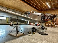
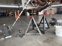
Finally installing my wheel pants and gear leg fairings, so I need a way to lift the tailwheel and level the fuselage... but also I need to keep the plane from nosing over while it's on the jacks, since the lift points are awfully close to the CG. I have a Tail Lift, but it's not really designed to pull downwards, and I didn't want to overload it with ballast.

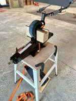
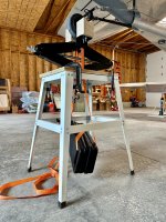
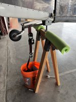
Lots of ways to do this, but here's mine. The base is a steel tool stand with a temporary plywood top, onto which is bolted a Harbor Freight scissor jack. I made some wooden supports that capture the tailwheel fork. A brace of cast iron weights are strapped to the fork; the straps pass straight down through the plywood.

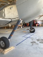
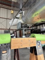
This ended up working great - with the wings raised just enough to get the tires clear of the ground, I only have to extend the scissor jack a couple inches to level the longerons. The lifting motion is straight up and the ballast straps go straight down, so nothing is side-loaded. And unlike the hydraulic jacks under the wings, the tail height is precision-adjustable.

Best of all, I got to use up a chunk of hardwood I've been holding onto for fifteen years and three mailing addresses...!
 

Attachments

  • IMG_7815.jpeg
    IMG_7815.jpeg
    3 MB · Views: 178
  • IMG_7811.jpeg
    IMG_7811.jpeg
    4.2 MB · Views: 179
  • IMG_7813.jpeg
    IMG_7813.jpeg
    5 MB · Views: 179
Just wondering how an alternative idea may work for you.... Hook an engine cherry picker to the lifting eye of your engine & jack it up with about 100lbs force while keeping jacks under wing points - this will just change cg aft so you could use you tail lift without all the other stuff. Just an idea.
 
Great idea.
I'm about to do the same to my Rocket:
-did you use the Van's process?
-any additional tips ? Lasers? Extra strings?
 
I did think about using my engine hoist, but... it's hard to judge how much force is being applied, and I certainly wouldn't want to put more than 1 engine worth of pull on that little ring!
Put a bathroom scale under tail wheel, tug on engine till tail wheel scale shows about 70lbs (or match the weight from your W&B numbers), will not take much of a tug...
 
I'm about to do the same to my Rocket:
-did you use the Van's process?
-any additional tips ? Lasers? Extra strings?
Last time I did this I used strings and sticks, but this time I've borrowed some good ideas from VAF - I'll post some pictures when I'm done.

Put a bathroom scale under tail wheel, tug on engine till tail wheel scale shows about 70lbs (or match the weight from your W&B numbers), will not take much of a tug...
Nah, I don't trust an engine hoist to stay put for the duration.
 
To keep it from nosing over while level on jacks- A couple cases of oil (50lbs) stacked on the Horizontal Stab will do it. 3 cases if you have is better yet.
I’ve done this on 6/7/8s & Rockets
 
I tie the tailwheel down to my tail lift and use a small piece of plywood with a heavy vice on it for ballast.
No, it wasn’t designed for that but I have not had any issues. My 6 will fly the tail but it won’t nose over on its own.
When someone was asking for feedback on building a tail lift I suggested they incorporate a way to weigh down the lift and clamp the tail but they didn’t incorporate that into the new design.

I like what you have done. Part of the fun of building is thinking of creative ways to solve problems.
 
Thats really clever and best of all, probably didn't cost a lot or take a bunch of time to set up.

Like you said, there's lots of ways to skin this cat. In my case, I had pre-fit my wheel pants in the garage before the engine was on, but when I reinstalled everything in the hangar I elected to blow off getting it off the ground for the leg fairing alignment because of the nose over tendency you identified, and also because I didn't have a pair of jacks available that day.

I used the string method that vans calls out, but with the mains on the ground and the tail up on my tail lift. That got me pretty close. Then just before I flew it that way I applied some home made flight test marking dye to the leading edges of the leg fairings. The yaw was maybe 1/8 ball out in flight and when I landed and looked at the streak pattern I could see one of them was off slightly.

Adjusted, reapplied new marking dye and flew again. All good.

I felt like that was a lot easier and quicker for me to just go fly than waiting to borrow a set of wing jacks and trying to devise something to keep it from face planting while I was working by myself.

Here's a post flight picture.
 

Attachments

  • IMG_9972.jpeg
    IMG_9972.jpeg
    1.6 MB · Views: 81
I applied some home made flight test marking dye to the leading edges of the leg fairings. The yaw was maybe 1/8 ball out in flight and when I landed and looked at the streak pattern I could see one of them was off slightly.
Cool idea. For future reference, is there a particular kind of dye that worked best?
 
On the 8, RV (the other kind ) leveling jacks on the forward gear bolts work well. Concrete blocks are cheap (Gear alignment check and tweak)1744478070544.jpeg
 
Thats really clever and best of all, probably didn't cost a lot or take a bunch of time to set up.

Like you said, there's lots of ways to skin this cat. In my case, I had pre-fit my wheel pants in the garage before the engine was on, but when I reinstalled everything in the hangar I elected to blow off getting it off the ground for the leg fairing alignment because of the nose over tendency you identified, and also because I didn't have a pair of jacks available that day.

I used the string method that vans calls out, but with the mains on the ground and the tail up on my tail lift. That got me pretty close. Then just before I flew it that way I applied some home made flight test marking dye to the leading edges of the leg fairings. The yaw was maybe 1/8 ball out in flight and when I landed and looked at the streak pattern I could see one of them was off slightly.

Adjusted, reapplied new marking dye and flew again. All good.

I felt like that was a lot easier and quicker for me to just go fly than waiting to borrow a set of wing jacks and trying to devise something to keep it from face planting while I was working by myself.

Here's a post flight picture.
Is it very evident in the dye markings where the flow attachment line/stagnation point is?
 
Cool idea. For future reference, is there a particular kind of dye that worked best?
You can mix some powdered tempura paint into motor oil. It is hard to get it totally smooth, it will be kind of gritty. I've had modest success straining it through a coffee filter. It will wash off with a little bit of solvent even if it dries. Or just use some old dirty crankcase oil.
 
On the 8, RV (the other kind ) leveling jacks on the forward gear bolts work well. Concrete blocks are cheap (Gear alignment check and tweak)View attachment 85018

Yeah, but seriously, roll those concrete blocks 90 degrees so the web holes are vertical. They are very prone to collapse when loaded as shown.
 
Cool idea. For future reference, is there a particular kind of dye that worked best?
Steve nailed it. Powdered paint from hobby lobby mixed with enough motor oil to give it consistency just a tiny bit less viscous than peanut butter.
 
Is it very evident in the dye markings where the flow attachment line/stagnation point is?
Yup

When I built the leg fairings I wanted to make sure the piano hinge stayed hidden, so I moved it fwd from the trailing edge a little bit. I don't remember exactly how much. Probably somewhere in the neighborhood of 1/4" from where it would align with the trailing edges just naturally coming together.

The result was that when installed around the gear tube you have to squeeze the two sides a bit to get the hinge eyes to align. The trailing edge is nice and tight, but it also makes the cross section a little bit of a teardrop shape instead of a more ideal airfoil. Right where the ellipse starts to get a little bit concave at the hinge is where the air separates.

If you look at the picture I attached it's very clear where the stagnation point is. You can see the dye starts to just run diagonally down the fairing at that point.

I probably lost .025 kts by creating that drag. Not enough to ever notice, but once I saw it I was kinda bummed that I had induced that.
 
Last edited:
Yup

When I built the leg fairings I wanted to make sure the piano hinge stayed hidden, so I moved it fwd from the trailing edge a little bit. I don't remember exactly how much. Probably somewhere in the neighborhood of 1/4" from where it would align with the trailing edges just naturally coming together.

The result was that when installed around the gear tube you have to squeeze the two sides a bit to get the hinge eyes to align. The trailing edge is nice and tight, but it also makes the cross section a little bit of a teardrop shape instead of a more ideal airfoil. Right where the ellipse starts to get a little bit concave at the hinge is where the air separates.

If you look at the picture I attached it's very clear where the stagnation point is. You can see the dye starts to just run diagonally down the fairing at that point.

I probably lost .025 kts by creating that drag. Not enough to ever notice, but once I saw it I was kinda bummed that I had induced that.
Sorry I think I wasn't clear enough. You seem to be talking about the separation point, most of the way back on the airfoil where the flow separates and the dye runs down spanwise. I'm talking about the leading edge attachment line, the point where the oncoming flow splits to go around both sides. The only benefit I see to using the dye on a flight test would be to be sure the attachment line is exactly on the leading edge, proving that the airfoil is aligned with the oncoming flow. If the attachment line is offset from the leading edge, it means that there is an angle of attack and the fairing will be creating lift.

Also you may be pleased to know that your dye flows do not show actual flow separation. They do show a distinct laminar-turbulent transition (the brownish blurry band-actually a small laminar bubble) and then a very slow velocity flow in the pressure recovery area. But as the dye runs spanwise because of the very slow flow, it does continue aft. That is good. If it were true separation, it would show a recirculation area where the dye flows forward. What you have is pretty low drag. But it will be very sensitive to bugs and rain and may actually separate if there is a lot of leading edge bugs. So keep it clean, and don't paint a pinstripe along the leading edge.
 
Last edited:
Sorry I think I wasn't clear enough. You seem to be talking about the separation point, most of the way back on the airfoil where the flow separates and the dye runs down spanwise. I'm talking about the leading edge attachment line, the point where the oncoming flow splits to go around both sides. The only benefit I see to using the dye on a flight test would be to be sure the attachment line is exactly on the leading edge, proving that the airfoil is aligned with the oncoming flow. If the attachment line is offset from the leading edge, it means that there is an angle of attack and the fairing will be creating lift.

Also you may be pleased to know that your dye flows do not show actual flow separation. They do show a distinct laminar-turbulent transition (the brownish blurry band-actually a small laminar bubble) and then a very slow velocity flow in the pressure recovery area. But as the dye runs spanwise because of the very slow flow, it does continue aft. That is good. If it were true separation, it would show a recirculation area where the dye flows forward. What you have is pretty low drag. But it will be very sensitive to bugs and rain and may actually separate if there is a lot of leading edge bugs. So keep it clean, and don't paint a pinstripe along the leading edge.
ah, gotcha. I misunderstood what you were asking.

Yeah, probably not the most precise way to define the exact leading edge separation point, but honestly, I think in this case it's good enough for government work. I tried to put drops of dye on the leading edge as defined as my calibrated eyeball. Then after flight I just looked to see if the amount of dye was symmetrical on both sides and if the length of the streak were about the same. after the first flight, one of the fairings had noticeably more paint on one side than the other. That seemed to support what I was seeing with the ball slightly out, so I adjusted accordingly, and on the second flight the ball was back in the middle and the paint streaks were in the ball park of symmetrical, so I called it good.

Thanks for the fancy engineer explanation of what's going on aerodynamically back there. It makes a lot of sense.
 
What timing. I’m tired of watching my 6A flying buddy pull away from me in cruise so after 1.5 years of flying, it's time to get the failings on! Started yesterday. Here’s how I’m skinning the cat.
 

Attachments

  • IMG_1637.jpeg
    IMG_1637.jpeg
    5.1 MB · Views: 30
  • IMG_1638.jpeg
    IMG_1638.jpeg
    2.7 MB · Views: 29
  • IMG_1639.jpeg
    IMG_1639.jpeg
    2.6 MB · Views: 30
Back
Top