Mike S
Senior Curmudgeon
Great news!!Just a note to say that the surgery seems to have done what it was supposed to
Stay tuned to this station!
Dave


Great news!!Just a note to say that the surgery seems to have done what it was supposed to
Stay tuned to this station!
Dave


It's good to see you back and pushing on with the build!Here I am back again.
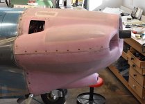
The cowl tool is working out just fine but this 2-day job is dragging; I haven't been working on the airplane. I got the cowl assembled and back on and found that the aft edge of the lower cowl needed trimming. I spent much of today doing that: mark where needed, remove, trim, install, repeat. But getting fairly close.
I've been using a bungee across the top of the engine mounts and down to two clips on the lower cowl to help support it while doing the removal/reinstallation. Here's a very poor photo, showing the bungee, the fitting and the ignition leads which are presently unconnected.
View attachment 58712
Here's a shot of the left-hand fitting:
View attachment 58713
On a different topic, my mentor called today with some comments about the exhaust hanger. The Vetterman exhaust came with the standard hose and tube arrangement, and the instructions said to attach it to this bar (the blue bar between the exhaust pipes). We discussed different approaches. Since I'd like to prevent vertical motion of the exhaust at this point, I'll have to build something with that in mind. It's still somewhat off in the future. I'll decide then if I want to connect it to the airframe of the engine; both appear possible, although hoses might get in the way.
View attachment 58714
Dave


")


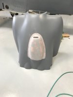
It is good that you are still making progress Dave. The FAB can be quite a bit of work. Here is a suggestion for an alternative way of connecting the ram air inlet to the FAB with a piece of SCAT instead of the baffle seal material. The SCAT flexes to accommodate the engine start/stop shake and the removable snout makes it easier when installing the lower cowl.The throttle, mixture and governor controls are hooked up. Can’t hook up the carb heat control just yet. The main impediments at this time are that the control’s firewall pass-through itself isn’t located, and the FAB hasn’t been built yet. Minor things.
View attachment 74883
Knowing that I’ll be installing and removing the bottom cowl numerous times, and maybe even the exhaust, to install it has thus far been what Robert Persig, I believe, has termed a “gumption trap.” I’ve decided to build and install the FAB anyway. Here’s the beginning photo showing the parts.
View attachment 74884
It’s been a while since I really worked on this project, so getting organized took some time.
The first thing that stopped me was the need for cutting the length of the FAB for my cowl. I attached the top plate to the carb, installed the lower cowl, and measured in from the air intake lip to that for a reference dimension. That gave me an accurate dimension for cutting it.
The distance still seemed excessive so I asked VAF for a sanity check, found I was sane enough to do this, and whacked it off.
View attachment 74885
After some positioning adjustment, I located and drilled the air box top plate, the aluminum part with the curvy flanges to the top plate. Once I drilled the rivet holes for those filter-retention clips, I found that either things were way off, or my 2013 filter had shrunk, as is their tendency. I have a request into VAF Support right now asking for their opinion.
View attachment 74886
Although I don’t have any photos of it, I determined how high the front of the FAB snout should be raised and fluted the sides of the banjo-shaped bent plate to raise it that much.
Dave

Haaa, the famous shrinking filters... not really uncommon, though I only thought it'd happen when in service, e.g. engine running/flying. Great work Dave, as usual.It is good that you are still making progress Dave. The FAB can be quite a bit of work. Here is a suggestion for an alternative way of connecting the ram air inlet to the FAB with a piece of SCAT instead of the baffle seal material. The SCAT flexes to accommodate the engine start/stop shake and the removable snout makes it easier when installing the lower cowl.
View attachment 74888
I made mine removable and it is much simpler to put the lower cowl on.Haaa, the famous shrinking filters... not really uncommon, though I only thought it'd happen when in service, e.g. engine running/flying. Great work Dave, as usual.
Yes, a removable snout or lower cowl part would sure be the way to go, and what I'll do on my next build.
In my next life that is.
I had a removable inlet on the RV 10, and thought about splitting the lower cowl also. With a 3 blade prop it would have been a great mod. Really easy to do too.Hypothetically, with a removable snout like that, it might be possible to split the lower cowling on the vertical centerline and then it might be much easier to remove and reinstall. Just wondering.


Mine is like that also, there is an oval plate that holds the filter via 6 long bolts and there is clearance between the plate and the fiberglass bowl. My FAB kit was from Van's in 2000 and it appears the design was changed since then to eliminate the plate, hence the contact and wear problems that some people experience.My O320 filter does not contact the fiberglass. It has a plate on the bottom of the filter and gets bolted up to the top plate. This leaves a space between the plate and the bottom of the FAB. Your inlet is smaller than mine. You may try to fit the carb heat flap and see. Your air box may need to be lowered.


Well, you looked pretty fit to me 2 1/2 years ago... keep going!I’ve also got a daily exercise and workout program and a weekly stretching arrangement, and all in all, feel pretty darn good. How far that'll take me, who knows?
")
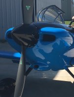
Box and air intake look great!After some fuss and bother, I finally got the FAB together. The somewhat oversized flapper valve works and seals both closed and open.
View attachment 82259
View attachment 82260
View attachment 82261
I’m using Robbins Wings carb and cabin heat hardware. You can see that I haven’t yet removed all my markings.
There were two articles, one in Kitplane and one in Sport Aviation, on quitting flying due to age-related medical issues. The two articles arrived here within a week of each other and together made me thing hard about flying, as I’m closing in on the ages of the writers, being in my late 70s. So for what it’s worth, yeah, I’ve got some issues but I’ve also got a daily exercise and workout program and a weekly stretching arrangement, and all in all, feel pretty darn good. How far that'll take me, who knows?
Dave

I like the story about Clayton Scott, born in 1905, a long time aviator who was Bill Boeing's personal pilot for eight years in the 30s, who then became a long time test pilot for Boeing. He was the first pilot to land on Boeing Field, before it was official opened. In 2005 he flew a twin-engine Aerostar into Boeing Field to attend a celebration at the Museum of Flight where the nearby Renton Airfield was named in his honor. This airfield is adjacent to Boeing production facilities where the first B29s were built. His pilot certificate was #2255, the lowest numbered active certificate. Not only was the celebration in honor of Renton Airfield being named for him. It was his 100th birthday...After some fuss and bother, I finally got the FAB together. The somewhat oversized flapper valve works and seals both closed and open.
View attachment 82259
View attachment 82260
View attachment 82261
I’m using Robbins Wings carb and cabin heat hardware. You can see that I haven’t yet removed all my markings.
There were two articles, one in Kitplane and one in Sport Aviation, on quitting flying due to age-related medical issues. The two articles arrived here within a week of each other and together made me thing hard about flying, as I’m closing in on the ages of the writers, being in my late 70s. So for what it’s worth, yeah, I’ve got some issues but I’ve also got a daily exercise and workout program and a weekly stretching arrangement, and all in all, feel pretty darn good. How far that'll take me, who knows?
Dave


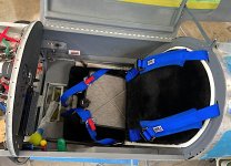
Any concern about chafing the shoulder straps where they come through the bulkhead?The seat belt and shoulder harness arrived from Crow and I installed them. This included a crotch strap.
View attachment 82758
1. The sewn-on shoulder harness pads are very thick and I don’t know yet if I’ll get rid of them. They are comfy, though, and so far feel great.
2. The plane’s mounting points on the turtledeck above the baggage area need to be made to fit a bolt and nut and washer. I’d done that, and installed them okay, but had to install the bolt pointing up because I could get the nut into the space but not the whole bolt. No biggie.
3. I had to use the work platform I’d made years ago to do the install, laying on my back. Getting in and out was harder than it was back then, mostly because I’d forgotten the routine bends and twists, but also because the cockpit is more mature now and more things are in it.
4. The bottom outboard corners of the seat back needed trimming to clear the seat belt attachment fittings. They already cleared the plane’s mounting points. I had to rim the corners about 1/2” for this.
View attachment 82759
5. Somewhere along the way, I misunderstood the thickness of the bottom crotch strap attachment fitting and made it so a 1/16” bracket and perhaps a .090” bracket would fit. As received, it was just under 1/8”. I called Crow and their recommendation was to grind the bracket’s tang down. As this seemed easier than remaking the plane’s mounting point, I did that. It wasn’t too hard. Primed and baked it and installed it.
I’d thought that the 2’ wide crotch strap would chafe or worse, but on the RV-3B, the rudder pedals are wide enough and my legs spread enough, so that is a complete non-issue.
6. Crow sent me a belt and harness for the RV-4 or RV-8, and it fits, with some adjustment needed. The adjustment capability was there and I trimmed off 24” excess belt length, cumulatively. The straps still allow for a considerably larger pilot than I am. The shoulder harness straps did not need trimming.
7. I’d ordered the 2” aluminum adjusters and was told that they absolutely hold and don’t slip. They are a bit awkward to work and I wouldn’t make that choice again. I need to press the barrel adjacent to the lift tang to make it work. Plus, they stick out about 1 3/4” from the harness belt’s surface. I didn’t know these things when I ordered this. Frankly, I don’t care for them. They can be operated one-handed, though.
View attachment 82760
Yes, that's me in the photo. A rare selfie.
8. I thought I ordered the black hardware but unfortunately it came with the standard silver, except for the adjusters. A miscommunication.
9. I placed the order on Monday just after noon Mountain time and when I got up Wednesday morning, the box was on my front steps. Amazing service. Also, they are easy to talk with.
10. I ordered the blue, expecting to receive a navy blue system. Instead, it’s a bright cobalt blue. This is fine, just unexpected. Color samples might be in order if you care about a particular color.
View attachment 82762
Dave
Yes. I need to add anti-chafe to that.
Dave

Looking good Dave. Looks like you are getting closer!!The seat belt and shoulder harness arrived from Crow and I installed them. This included a crotch strap.
View attachment 82758
1. The sewn-on shoulder harness pads are very thick and I don’t know yet if I’ll get rid of them. They are comfy, though, and so far feel great.
2. The plane’s mounting points on the turtledeck above the baggage area need to be made to fit a bolt and nut and washer. I’d done that, and installed them okay, but had to install the bolt pointing up because I could get the nut into the space but not the whole bolt. No biggie.
3. I had to use the work platform I’d made years ago to do the install, laying on my back. Getting in and out was harder than it was back then, mostly because I’d forgotten the routine bends and twists, but also because the cockpit is more mature now and more things are in it.
4. The bottom outboard corners of the seat back needed trimming to clear the seat belt attachment fittings. They already cleared the plane’s mounting points. I had to rim the corners about 1/2” for this.
View attachment 82759
5. Somewhere along the way, I misunderstood the thickness of the bottom crotch strap attachment fitting and made it so a 1/16” bracket and perhaps a .090” bracket would fit. As received, it was just under 1/8”. I called Crow and their recommendation was to grind the bracket’s tang down. As this seemed easier than remaking the plane’s mounting point, I did that. It wasn’t too hard. Primed and baked it and installed it.
I’d thought that the 2’ wide crotch strap would chafe or worse, but on the RV-3B, the rudder pedals are wide enough and my legs spread enough, so that is a complete non-issue.
6. Crow sent me a belt and harness for the RV-4 or RV-8, and it fits, with some adjustment needed. The adjustment capability was there and I trimmed off 24” excess belt length, cumulatively. The straps still allow for a considerably larger pilot than I am. The shoulder harness straps did not need trimming.
7. I’d ordered the 2” aluminum adjusters and was told that they absolutely hold and don’t slip. They are a bit awkward to work and I wouldn’t make that choice again. I need to press the barrel adjacent to the lift tang to make it work. Plus, they stick out about 1 3/4” from the harness belt’s surface. I didn’t know these things when I ordered this. Frankly, I don’t care for them. They can be operated one-handed, though.
View attachment 82760
Yes, that's me in the photo. A rare selfie.
8. I thought I ordered the black hardware but unfortunately it came with the standard silver, except for the adjusters. A miscommunication.
9. I placed the order on Monday just after noon Mountain time and when I got up Wednesday morning, the box was on my front steps. Amazing service. Also, they are easy to talk with.
10. I ordered the blue, expecting to receive a navy blue system. Instead, it’s a bright cobalt blue. This is fine, just unexpected. Color samples might be in order if you care about a particular color.
View attachment 82762
Dave
David - we just built a doubler out of 0.060” (or maybe a little thicker), riveted it on, and then radiused the slot all the way around - have never had any chafing problems on the harness. Going on 13 years and just shy of 900 hours…..Yes. I need to add anti-chafe to that.
Dave