Van's Air Force

The definitive Van's Aircraft support community! Buying, building or flying an RV? Join our exclusive family of mentors and enthusiasts!

Ground location

JDA_BTR

Well Known Member
Patron
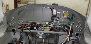
RV-8 with an aft battery and battery contractor. I'm going to put the lighting controller, the ADAHRS, and a few other boxes aft. Maybe a COM2 remote radio aft. Maybe keep the audio controller aft as well if I remote it. I'll feed the aft circuits through a fuse block.

I need a ground bus plan. I don't want to run all the ground wires forward to the firewall, and I don't want to run all the forward circuit ground wires aft.

So maybe two ground tab plates. One forward at the firewall, and another aft tied to the battery ground. Any box that has audio associated in any way can run its ground aft to avoid loops. The only thing forward with audio in this setup is a COM1/Nav radio, and the G3X display. Everything else up forward can ground up forward at a firewall tab plate.

I like having the lighting controller, audio panel and remote radio aft, since then the headset jacks and stick button wiring and a lot of other wires don't have to go across the spar.

I know there are a million opinions on all this. What I'm really after is has anyone split out the grounds this way?
 
Having two ground points drawing different currents is a ground loop by definition. Can you get away with it? Probably. It’s just so much less hassle over the life of the airplane to make sure all the individual loads are at the same ground potential.

I think all RV8 builders need to review the aft battery location. It was a thing when batteries weighed 25 pounds. Using a modern lightweight battery negates the change in CG. I did aft battery. If I did it again I would use an EarthX in the forward baggage compartment. you loose 4 pounds of wire.

The aft battery location is awesome for remote avionics components. Just run the handful of grounds from the same battery connection.
 
Last edited:
The EarthEx batteries weigh about 4lbs, 1.8kg. I was seriously looking at the aft configuration, even with the EarthEx because it looks like I'm having to go with the heavier AV engine, but having run some numbers I'm not going to bother.
 
The EarthEx batteries weigh about 4lbs, 1.8kg. I was seriously looking at the aft configuration, even with the EarthEx because it looks like I'm having to go with the heavier AV engine, but having run some numbers I'm not going to bother.
I want the weight aft.... and less cross-spar wiring it permits too.
If you mount a tab ground plate aft where do you mount it best? My battery ground cable ties into the left lower longeron left of the aft battery.
 
Last edited:
I want the weight aft.... and the not-cross-spar wiring it permits too.
If you mount a tab ground plate aft where do you mount it best? My battery ground cable ties into the left lower longeron left of the aft battery.
With the Aft battery you’re going to have to run a substantial cable across the spar to the engine anyway. So there’s not much in it is there?

As for aft grounding, I think the lower longeron is probably best location. I’m looking at keeping the battery fwd, but using the aft battery location to mount some avionics.
Yes, the #2 +12V goes forward for the starter and such, that isn't a problem. But I will ground the engine to the firewall I'm not worried about that. Same idea with lights and pitot heat that will ground at the wing root.

I suppose I could run a #10 forward from an aft ground point, and make up a 15 pin dsub for the forward electronics to ground to. Or vice versa.

So another question to contemplate. I'll have a GAD27 aft, because everything it does (almost) is aft. If I don't ground it or the things it controls to a common ground point, is there any risk of an audio ground loop. This is flaps, lights, trim mixer, power continuity circuit, discretes. I don't think it would matter at all.

It is easy to not worry about it when every single thing grounds at one place. But on the other hand, we know that not everything must. I think by having everything associated with an audio feature grounded at one point the problem is solved. But I'm looking to see if anyone else has tinkered with this.

Dynon has an article on it:

I'll probably end up fashioning a single common ground for everything but just thinking on it..... The forest of tabs at the firewall is the single easiest place to ground a lot of things.
 
I suspect once you figure out the cable runs to all the stuff you want to put back there, adding a ground wire for each is trivial. I also suspect the other connections might not make mounting your full list aft worth while.

For example my aft mounted Dynon stuff:
- Single 9 wire network cable (has a ground in it)
- Autopilot pitch servo (single four #22 shielded cable, one #20 power, one #20 ground, one #22 disengage wire)
- ADS-b receiver, single four conductor shielded cable and a short coax to the aft mounted ADS-b antenna

For remote audio panel and remote comm, if you plan on mounting something like a GTN-650 on the panel you are going to have a problem integrating a remote audio panel. Additionally if your remote comm has a panel control module (like the Dynon radio) you will have significant interconnection cable to route.

The photo shows how I mounted the remote Comm #2 and XPDR behind the panel in my RV-8 (the brass colored modules). You will find the audio panel will have a boatload of interconnections as well. My point - there should be plenty of room to mount this stuff forward. The wiring is much easier and the impact to W&B is in the grass.

I have one PC-625 battery mounted aft and one mounted in the forward baggage well. With the IO-360-M1B and standard Hartzell BA prop the W&B works out well.

Carl
 

Attachments

  • IMG_0680.jpeg
    IMG_0680.jpeg
    545 KB · Views: 63
I'm no engineer, but I thought the full load of the starter flows positive to negative. If there's no cable to the battery ground, the airframe carries the load. It could also find another path of least resistance. I'm sure I'm wrong.
I considered an equal sized cable from starter ground to the battery ground point, but decided against it. I have a large braid from the engine to the ground point. All gounds to one FOT inside and out bonded together. My battery is FWF though.

In simplest terms -- the "size" of the return wire should be equal to the supply wire. In any given circuit, you'll want to do the math to determine the acceptable voltage drop for the load and size the wire (supply and return) accordingly.

Typically, the supply wire from the battery to the starter is 2AWG. The braided strap that Van's provides to connect the battery to the ground lug/firewall is 2AWG. Connecting a similarly sized strap from the engine to the firewall is correct practice.

Our aluminum airframes are an excellent conductor, and has an AWG equivalency of at least 2, possibly lower. TLAR was derived by analyzing the average cross section of the aluminum structures from firewall to aft bulkhead.

In practice - In my RV-7s, the only loads that have a "dedicated" ground wire (i.e. ground wire running from load to a point proximal to the buss supply, firewall lug) are the Garmin GSA 28 servos (because that what Garmin directed, and not because it was necessary -- can argue about this later...).

Everything else (Landing/Taxi Lights, Strobe Lights, Fuel Pump, Avionics) has the ground wire attached to the airframe at a nearby location with the following exceptions:
1. I used a twisted pair (supply+return) for the Pitot Heat to prevent the EMF in the wire from interfering with the GMU located in the wing (RV-14).
2. Headphone and Mic Jack shields only terminate to ground at the audio/intercom. The jacks are further isolated from the airframe with isolation/shoulder washers.
I also used frame grounds on both my planes with zero negative effects, including the garmin servos. I did use a common ground bus on the firewall for avionics or anything that I deemed sensitive to electrical noise. Behind the panel , these wires are short, so no disadvantage. The batteries on my 10 are in the back and use simple frame grounds back there. One exception was the flyled lights. His emi strategy is bringing grounds back on the shield wire and followed that recommendation.
 
Last edited:
It’s called experimental because …. There’s nothing inherently wrong with what you are proposing- you’d like to optimize some features important to you. The single point ground is what is called a best practice in the engineering world, which means follow these rules and you’ll be safe. The single point ground protects the millivolt level circuits from ground loops- engine instruments and the famous audio whoop whoop . If you are careful with the audio ground and all your engine instruments are three wire: supply-output-ground where again you do the ground right, things should work out ok. The thing about breaking the rules is you need to think of all the consequences in advance so you don’t have to rip up things after the fact. 😀
 
It’s called experimental because …. There’s nothing inherently wrong with what you are proposing- you’d like to optimize some features important to you. The single point ground is what is called a best practice in the engineering world, which means follow these rules and you’ll be safe. The single point ground protects the millivolt level circuits from ground loops- engine instruments and the famous audio whoop whoop . If you are careful with the audio ground and all your engine instruments are three wire: supply-output-ground where again you do the ground right, things should work out ok. The thing about breaking the rules is you need to think of all the consequences in advance so you don’t have to rip up things after the fact. 😀
agreed, but I believe these best practices have some variability as well and not as simple as "only use one grd point.". For example, my toyota is pretty well engineered from a wiring perspective, with many devices sensitive to EMI and ground loops; Even has a decent amount of shielded wire. They do use common ground points, but there are many of them (>10), with several exceptions where grounds are individually attached to the frame. Grounds all go to common points for attachment to frame, but it is not a single common point. It is more of a hierarchy, with many ground points/hubs attaching to the frame as the master ground point/hub.

I agree fully that if care is not exercised in this area, problems can arise. I just wanted to make the point that it is not necessarilly required to install 100's of feet of ground wire to get EVERY wire back to a single, unique grd point. Once you start running numerous 20' ground wires in a bundle with other stuff, you run a risk that the cure is more problematic than the symptom, as you risk introducing EMI while trying to prevent ground loops..
 
Last edited:
agreed, but I believe these best practices have some variability as well and not as simple as "only use one grd point.". For example, my toyota is pretty well engineered from a wiring perspective, with many devices sensitive to EMI and ground loops; Even has a decent amount of shielded wire. They do use common ground points, but there are many of them (>10), with several exceptions where grounds are individually attached to the frame. Grounds all go to common points for attachment to frame, but it is not a single common point. It is more of a hierarchy, with many ground points/hubs attaching to the frame as the master ground point/hub.

I agree fully that if care is not exercised in this area, problems can arise. I just wanted to make the point that it is not necessarilly required to install 100's of feet of ground wire to get EVERY wire back to a single, unique grd point. Once you start running numerous 20' ground wires in a bundle with other stuff, you run a risk that the cure is more problematic than the symptom, as you risk introducing EMI while trying to prevent ground loops..
You are spot on! 😀 A 747 is too large for a single point ground so it uses a bunch of single point grounds flying in formation. The OP wants to do the same thing which is kind of cool. So you single point ground a sub system to guard against ground loops which is what you and the OP are talking about.
 
I'm no engineer, but I thought the full load of the starter flows positive to negative. If there's no cable to the battery ground, the airframe carries the load. It could also find another path of least resistance. I'm sure I'm wrong.
I considered an equal sized cable from starter ground to the battery ground point, but decided against it. I have a large braid from the engine to the ground point. All gounds to one FOT inside and out bonded together. My battery is FWF though.
The starter grounds to the engine, which has a ground strap to the firewall, and from there to the battery ground strap to the battery. On an -8 with an aft battery that ground strap is aft so the current goes how it wants from the firewall to the battery strap. But there is so much aluminum from the firewall to the battery strap that there is low or no potential between the two.
 
agreed, but I believe these best practices have some variability as well and not as simple as "only use one grd point.". For example, my toyota is pretty well engineered from a wiring perspective, with many devices sensitive to EMI and ground loops; Even has a decent amount of shielded wire. They do use common ground points, but there are many of them (>10), with several exceptions where grounds are individually attached to the frame. Grounds all go to common points for attachment to frame, but it is not a single common point. It is more of a hierarchy, with many ground points/hubs attaching to the frame as the master ground point/hub.

I agree fully that if care is not exercised in this area, problems can arise. I just wanted to make the point that it is not necessarilly required to install 100's of feet of ground wire to get EVERY wire back to a single, unique grd point. Once you start running numerous 20' ground wires in a bundle with other stuff, you run a risk that the cure is more problematic than the symptom, as you risk introducing EMI while trying to prevent ground loops..
Yes this is often overlooked: the induced EMI in long ground wires.
 
I've been changing my thinking about remote boxes. I still will put the lighting controller aft, because that is where it does all its work. But I'll mount the remote radio and the audio panel forward on a sub panel tray behind the G3X display. Just easier to get to that way. Also have to find a place for the GEA24 and Arinc box.... So many boxes.
 
Back
Top