

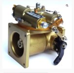
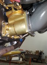
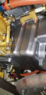
I built my Lycloning engine with 10:1 compression, Superior cold air sump, dual Lightspeed ignitions, and an FM-150 fuel servo. I recently posted a thread about going to smaller injectors. My problem predates the .024 injector installation but seems to have gotten worse. For some time, I've noticed a stumble when coming off idle and applying takeoff power. It clears up immediately once I get some significant RPMs and I really hadn't been viewing it as a bad problem, but it is getting worse and I've got to jockey the throttle to pass 12 or 1300 RPM.
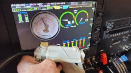
To add to the mystery/symptom list, when I pull to idle the MAP actually increases to about 20" from about 16" at 1000. Should be more like 10. To tell the truth, I can't say it hasn't done that for a long time because I just started looking at that. Don at AFP said to check the throttle opening pulled to the idle stop, looking for .004 - .008. I measure .006. Pulled hard to the stop she idles about 600RPM, and as is typical, smoother at 700-750. I'm going to see if I can't figure a way to check the MAP indication somehow. Another data point is that I adjusted the idle mixture so that the linkage is as short as it can go and I still get about 200 RPM rise at ICO.
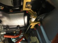
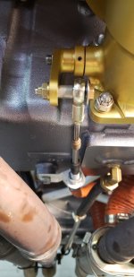
I suspected an induction leak and found fuel staining and a wet hose at one of my intake tubes. I replaced it and the gasket with no change to the symptoms. I'll do the other ones, but I'm not expecting much. Don thinks I might have an ignition problem so that's next. I tried to strobe the timing today, but the light wasn't bright enough and the marks weren't clear enough to see much in bright sunshine. I'll improvise a shade and try again after I replace the harness. I'll do new spark plugs and wires and check the coils for resistance.
Compressions tested in the high 70s a month ago.
Ideas?
Ed
To add to the mystery/symptom list, when I pull to idle the MAP actually increases to about 20" from about 16" at 1000. Should be more like 10. To tell the truth, I can't say it hasn't done that for a long time because I just started looking at that. Don at AFP said to check the throttle opening pulled to the idle stop, looking for .004 - .008. I measure .006. Pulled hard to the stop she idles about 600RPM, and as is typical, smoother at 700-750. I'm going to see if I can't figure a way to check the MAP indication somehow. Another data point is that I adjusted the idle mixture so that the linkage is as short as it can go and I still get about 200 RPM rise at ICO.
I suspected an induction leak and found fuel staining and a wet hose at one of my intake tubes. I replaced it and the gasket with no change to the symptoms. I'll do the other ones, but I'm not expecting much. Don thinks I might have an ignition problem so that's next. I tried to strobe the timing today, but the light wasn't bright enough and the marks weren't clear enough to see much in bright sunshine. I'll improvise a shade and try again after I replace the harness. I'll do new spark plugs and wires and check the coils for resistance.
Compressions tested in the high 70s a month ago.
Ideas?
Ed


![20250410_141338[1].jpg](/data/attachments/63/63600-d553fe6ed314f92eb78073e4951e0b3e.jpg?hash=4as47uV2C0)
![20250411_122828[1].jpg](/data/attachments/63/63601-d79294079c589404579fa4d32f97f6b7.jpg?hash=Bc6W3nAms7)
![20250411_122938[1].jpg](/data/attachments/63/63602-fb39eadc6c5c83ce81553345be440c8b.jpg?hash=EYVwji1idf)
