Van's Air Force

The definitive Van's Aircraft support community! Buying, building or flying an RV? Join our exclusive family of mentors and enthusiasts!

Alternator not charging, SCHEMATIC or guidance please... RV-4 / O-320 /

FabricGATOR

Active Member
So, I am somewhat IMC on this.
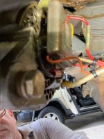
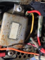
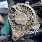
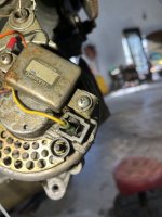
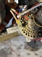
I believe it is a Nippon Denso (ND) alternator with a ND regulator attached to the back of the alt case.
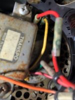
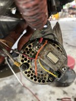
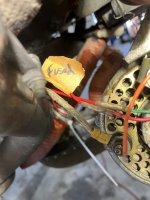
I see an orange wire broken or just cut clean.
I see the heavy lug connected to what I presume is direct to charging the (+) battery post
Then, the builder used three RED wires from the pasta bowl under the turtle deck forward to the alternator.
It all gets a little confusing sussing out all the reds (red seemed to be what was on hand that day of the build as it was used a bit)

Can anyone advise how I can test at the alternator and regulator wiring (either static or engine running) and then chase whatever doesn't check out?

How do I go about hot flashing (for lack of the better term) the alternator to momentarily test the alternator to determine if it will charge if the regulator is able to be controlling it properly?

I do have some notes:
F-7078 (maybe the regulator p/n - info)

581200-1641
s/n 0210006851 (maybe alternator info)?

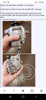
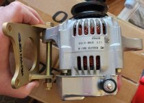
Is there perhaps a better alternator with internal regulator that might be better to replace this with?

I prefer to get this system working if it can be reliable and robust.

It may simply be a disconnected wire.
This ole bird sat dormant for at least a few years in humid Florida though mostly hangered AFAIK

Thank you to all who reply (and even those who look, just to see if they can answer :) )
 
Just to find out if the alternator is functional remove it and carry it to your local auto parts store, they can test it and possibly identify it.

There are good internally regulated automotive alternator options if you wish to pursue that path. A photo of what you have would be useful. :)
 
Did it quit on you, or is this a plane you havent flown? The more details the better. I have Denso with built in regulator on my -4. The heavy wire is the 12V "out" feeder. There should be 2 other smaller wires, one of which is to energize the field off the battery. If its not energized, you will get no output. the other wire is for a voltmeter. I have had the spade fitting crack under the plastic protector while in flight and lost charging..easy fix, I had theother spade do same thing and lost voltmeter even know it was charging , another easy fix. If you have a switch for the alternator field, like I do and most others do, make sure its all working.
 
This is a new to me aircraft purchased with issues, one being out of annual and the alternator did not charge when engine started.
The external voltage regulator is attached to the back of the alternator.

IIRC, there is a way to put 12 volts to the field somehow and then watch the voltage spike unregulated to 16+ vdc
That proves the alternator.

Likely the 'kids' at the auto parts would be a confounded by this ancient technology as I am. I am on my own... unless someone here recognizes these parts
 

Attachments

  • IMG_3015.jpg
    IMG_3015.jpg
    61.4 KB · Views: 90
  • IMG_3013.jpg
    IMG_3013.jpg
    53.9 KB · Views: 90
  • IMG_3014.jpg
    IMG_3014.jpg
    50.9 KB · Views: 92
This is a new to me aircraft purchased with issues, one being out of annual and the alternator did not charge when engine started.
The external voltage regulator is attached to the back of the alternator.

IIRC, there is a way to put 12 volts to the field somehow and then watch the voltage spike unregulated to 16+ vdc
That proves the alternator.

Likely the 'kids' at the auto parts would be a confounded by this ancient technology as I am. I am on my own... unless someone here recognizes these parts
Everything else (except the heavy wire to the battery) is red 16 ga wire from the firewall. I believe there are three additional red wires plus the #6 ga wire

I found this online, now how would it be installed if it had an alternator switch?
 

Attachments

  • atpinst_1024x1024@2x V_reg Transpo.webp
    atpinst_1024x1024@2x V_reg Transpo.webp
    48.4 KB · Views: 50
  • 51SwEt9LkEL._AC_SX425_.jpg
    51SwEt9LkEL._AC_SX425_.jpg
    16.7 KB · Views: 49
  • W112107-2_1024x1024@2x.webp
    [email protected]
    33.2 KB · Views: 49
Last edited:
This is a new to me aircraft purchased with issues, one being out of annual and the alternator did not charge when engine started.
The external voltage regulator is attached to the back of the alternator.

IIRC, there is a way to put 12 volts to the field somehow and then watch the voltage spike unregulated to 16+ vdc
That proves the alternator.

Likely the 'kids' at the auto parts would be a confounded by this ancient technology as I am. I am on my own... unless someone here recognizes these parts
Don't give up on the auto parts store yet. Checking an alternator on their machine is usually pretty much a plug-n-play operation. That check will most likely be more useful that trying to figure out wiring that goes who knows where...........
 
Don't give up on the auto parts store yet. Checking an alternator on their machine is usually pretty much a plug-n-play operation. That check will most likely be more useful that trying to figure out wiring that goes who knows where...........
yeah, thanks for the guidance. Now I am seeing more about it and how that thing gets mounted and connected.
.
I just found this and it shows where the F, N, and E terminals are situated... I'll be an expert when I find all the puzzle pieces
1732337464437.png
 

Attachments

  • H640999e8431043bf9e4888dd80c62762L.webp
    H640999e8431043bf9e4888dd80c62762L.webp
    101.5 KB · Views: 2
That looks like the alternator I just removed, a hitachi 12124. It wasn't supplying enough power to charge the battery at idle, or even in cruise if I turned on pitot heat. When measuring it at full engine power it would only put out around 18-19 amps, even with a new regulator.

I ended up replacing it with a 40 amp from b&c.
 
It looks like the 35 amp alternator that was in the Vans catalog about 25 years ago. Outside diameter is 4.75 inches approx.

The F terminal receives power from the external regulator to power the alternator field. E is connected to earth i.e. ground. N is not connected. B is the output power to the battery and main bus.

20241123_133350.jpg
 
The Transpo regulator can be mounted remotely. I use the same one and put it on the cold side of the firewall. Charging voltage is adjust with an inset screw on the bottom and is best adjusted with the engine running. That is not possible with it mounted to the alternator itself. You would just run the 12v field wire from your alternator switch to the Transpo. The output of the Transpo goes to the F terminal. One wire on the Transpo connects to your main bus inside so it can sense and regulated voltage. The other connection is ground. There is a wire for a "Alternator Fail" light if desired. I monitor mine on an EFIS so I did not use that wire. The regulators are inexpensive, easy to adjust and available online. I think the one I have actually came from Walmart.com. Never seen one in a store but their website sells a lot I have not seen in the store.
 
That looks like the 35amp 14184 alternator that Vans sold for many years back in the day, it is externally regulated. I have been flying this alternator on mt RV-6 since 1999. Use the 14184 number at any auto parts store to find a replacement, they were originally on a 1978 Honda Civic CVCC, no air conditioning. A regulator for a 1975 Ford LTD works nicely with this alternator, generic number is VR166.
 
Last edited:
I just finished up installing a new 60a internally regulated Duralast 14824 unit to replace an old 30amp ER unit few weeks ago. Reach out if you have any questions or wiring concerns.
 
The aircraft is about 20 miles away at a fly-in estate's community. I got by there today but wasn't able to do much probing and wire chasing. I did take a few more pix but it won't help me now until I can get some distraction free time with her on a quiet afternoon.
 

Attachments

  • IMG_3015.jpg
    IMG_3015.jpg
    61.4 KB · Views: 21
  • IMG_3014.jpg
    IMG_3014.jpg
    50.9 KB · Views: 21
  • IMG_3013.jpg
    IMG_3013.jpg
    53.9 KB · Views: 21
That looks like the 35amp 14184 alternator that Vans sold for many years back in the day, it is externally regulated. I have been flying this alternator on mt RV-6 since 1999. Use the 14184 number at any auto parts store to find a replacement, they were originally on a 1978 Honda Civic CVCC, no air conditioning. A regulator for a 1975 Ford LTD works nicely with this alternator, generic number is VR166.
 
I have this combination of alt and reg. I have a problem getting regulators to last. Can you send me a wiring diagram of your setup. Thanks, Jim
 
When I bought my 9, there were some unlabelled switches on the panel. It was switch and look to find out what they were. Is there an alternator switch somewhere?
Just a thought before you dive too far into the wiring
 
When I bought my 9, there were some unlabeled switches on the panel. It was switch and look to find out what they were. Is there an alternator switch somewhere?
Just a thought before you dive too far into the wiring
Yeah, thank you for the heads up. i do have the split master switch. I ASSuME that it is as I would expect but perhaps there is a an Barney Fife switch that is veiled to me at this time. I will get into testing and sussing the wiring here either today or tomorrow.

I WILL OF COURSE reply here with my findings. I hate when a forum member has a fault, they reach out to the community and receive answers AND THEN the thread just goes cold... I can't count how many times I Giggled a fault, only to find just such a circumstance on various automotive, marine, household appliances, electronics, etc... forums. No solution, no punchline, no reply, and many times not even a thank you.

Cheers!
 
I have this combination of alt and reg. I have a problem getting regulators to last. Can you send me a wiring diagram of your setup. Thanks, Jim

Post #12 has a link to the info your need. I've never had a problem with regulator service life, they seem to be very reliable. However, the regulator case MUST have a good ground or you could see intermittent ops or a failure.
 
Well, finally here after the holiday weekend.
This is certainly not wired like we discussed

Transpo BLACK is grounded to the case of the alternator

Transpo RED is connected to fused (10a) powers on with master

Transpo YELLOW has a blade conn to ALT (N) terminal

Transpo GREEN goes to a relay (controlled by the alternator rockerswitch) and then goes back to a blade connector that I presume (was) on the ALT (F) terminal
*so green switched to the alternator field by [alt] rocker
[ presume it went to F because the only other blade is ALT (E)… ]

would it have worked like that?
 

Attachments

  • IMG_1605.jpeg
    IMG_1605.jpeg
    1.7 MB · Views: 33
  • IMG_1607.jpeg
    IMG_1607.jpeg
    1.6 MB · Views: 38
  • IMG_1608.jpeg
    IMG_1608.jpeg
    1.7 MB · Views: 37
  • IMG_1609.jpeg
    IMG_1609.jpeg
    1.8 MB · Views: 37
I'm afraid I can't help with the old Transpo regulator, never used one. If I was in your situation dealing with an old installation that has been stored for a long time and not knowing if the thing was even working when it was put away, I would pull out all the old stuff and install a new internally regulated alternator per post #13 and be done with it.

https://www.autozone.com/batteries-...rnator/p/duralast-alternator-14824/871772_0_0

The regulator goes away, you can ditch the alternator switch and relay and you have a life-time warranty on the alternator. You stated you wanted something reliable............... :)
I appreciate the suggestion, and I understand the approach, the technology.
I've pulled the married pair and intend on following your suggestion to bring it to auto parts to see if they can test it.
I am not really excited about reinventing the wheel on someone else's airplane. I just am hoping to repair/replace the broken part now that I know how it was wired and that the wiring is not compromised or blown fuse, etc...

More info to be posted soon as I can get it.
Cheers, and again, thank you all so much for your input.
Every comment is read and evaluated and greatly appreciated as YOU TEACH ME to understand this older technology.
Although I may have no replied to everyone individually, I do appreciate it, thank you.
FabricGATOR
 
Well, finally here after the holiday weekend.
This is certainly not wired like we discussed

Transpo BLACK is grounded to the case of the alternator

Transpo RED is connected to fused (10a) powers on with master

Transpo YELLOW has a blade conn to ALT (N) terminal

Transpo GREEN goes to a relay (controlled by the alternator rockerswitch) and then goes back to a blade connector that I presume (was) on the ALT (F) terminal
*so green switched to the alternator field by [alt] rocker
[ presume it went to F because the only other blade is ALT (E)… ]

would it have worked like that?
How about the smaller diameter black encircled stud on the alternator that has what looks like an insulator, the black plastic encircled stud?
It look like it is begging for a connection to something

I wish I had a schematic for the alternator so I could see what (should) be going on, so I can verify that it has everything that it needs to operate.
What are all those stud's, blade connections connected to inside the alternator...
 
OK Aviators and maintenance personnel...
Keep in mind that this whole exercise was an experiment.

I was able to verify that the alternator unit was able to be excited by hotwiring (momentarily) the F (field) terminal to 12vdc and witnessed the alternator A) the pulley shaft became magnetized (magnetically attractive) and B) while turning with a battery drill, and connected to a test battery I saw the voltage go from the static reading and then above.

Alternator case grounded to the (-) battery terminal
Alternator output lug connected to battery (+) terminal
Alternator [ F ] blade was intermittently touched to the battery (+) while rotating (with drill, anything)
DMM set to Volts DC between battery (+) and (-) reading static voltage and then an increase above static when field was hotwired

I presumed that the fault must be in the external regulator. Both Napa and Advanced auto parts did not stock this Transpo F-7078 regulator. Ordered online.
DEC 2024 dollars = $22 + $6 s&h

I connected F-7078 green to Blade terminal Alternator [ F ] ** Switched through the master [ALT] switch (relay)
Black to alternator case (ground/earth)
Red to fused (master switched) ( + )
Yellow to master BUS (voltage sense)

ops check - normal, no smoke seen

If anyone see fault in my connection, please advise here for both myself and future answer seekers.
Cheers!
 

Attachments

  • Screenshot_20230215-085158_Opera.jpg
    Screenshot_20230215-085158_Opera.jpg
    177.7 KB · Views: 32
  • 50DC0644-95EB-4897-8379-A97FDE974312.jpg
    50DC0644-95EB-4897-8379-A97FDE974312.jpg
    330.5 KB · Views: 32
  • 5B15A2FC-0513-46E6-B2C3-51E8309F8F06.jpeg
    5B15A2FC-0513-46E6-B2C3-51E8309F8F06.jpeg
    87.5 KB · Views: 32
If you have a problem, there are hundreds of certified planes running this $140. Denso thru field approval https://www.ase-supply.com/product_p/nd-021080-0760.htm

It is IR but works great and can be installed with the BandC mounting kit available from their website
Thank you.
I am currently not trying to reinvent the wheel on a 'not my airplane'
I'll repair what is there, good or bad, right or (not so right)... until a time when I can suggest mods, upgrades, and/or replacement.
Fix it if you can...
 
My RV-8 alternator diagram had the diode facing the wrong direction in the instructions. I caught it on installation, otherwise it wouldn't charge.
 
Back
Top