I'm in the early stages of the project described here. The landing gear are temporarily secured with hardware store bolts and awaiting permanent installation with AN hardware. This plane formerly had a Subaru engine which has been replaced with an O-360 and, of course, a new engine mount, into which the landing gear inserts. The original builder of the airplane strongly suggested that I check the alignment of the landing gear. Misalignment would indicate that the clocking of the gear as inserted into the engine mount is incorrect. Has anyone else ever encountered such an issue before? If so, how did you fix it?

Van's Air Force
You are using an out of date browser. It may not display this or other websites correctly.
You should upgrade or use an alternative browser.
You should upgrade or use an alternative browser.
Landing Gear Alignment
- Thread starter yahugh
- Start date

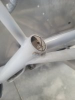
The bolt holes are drilled at the factory, so the alignment should be correct, unless the original builder had custom drilled gear legs for the Subaru mount. If that is the case, then I think that the solution would be to replace the gear legs.I'm in the early stages of the project described here. The landing gear are temporarily secured with hardware store bolts and awaiting permanent installation with AN hardware. This plane formerly had a Subaru engine which has been replaced with an O-360 and, of course, a new engine mount, into which the landing gear inserts. The original builder of the airplane strongly suggested that I check the alignment of the landing gear. Misalignment would indicate that the clocking of the gear as inserted into the engine mount is incorrect. Has anyone else ever encountered such an issue before? If so, how did you fix it?
How does the alignment of the axles look when the gear legs are fitted?
I'll have to install the real hardware and measure the alignment. I have more questions about this (please forgive my newcomer ignorance):The bolt holes are drilled at the factory, so the alignment should be correct, unless the original builder had custom drilled gear legs for the Subaru mount. If that is the case, then I think that the solution would be to replace the gear legs.
How does the alignment of the axles look when the gear legs are fitted?
- I'm told that the bolts are a precision fit. Is the bolt installation process documented anywhere? What is the torque spec?
- Any pointers on measuring wheel alignment?
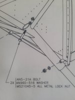
I do recall having to clean paint out of the holes in the motor mount. Other than that the legs just bolt up using a standard AN bolt as per the dwg above, torqued to 100-140" lbs.
My alignment was perfect right out of the box. Put the tires on greased plates. I measure in 3 point attitude although some do it in flight attitude. Draw a line from the center of the fuse front to back (I like to use a laser but chalk line and plumb bobs work fine). Clamp a long (at least 4') straight piece of angle, or what you have, to the brake disc and measure 90* at the axle to the centreline and again at the end of your bar. Calculate the angle from the difference in the two measurements. Do the same for both sides using the same measurement points. Vans specs 1/2* toe in for the round gear.
My alignment was perfect right out of the box. Put the tires on greased plates. I measure in 3 point attitude although some do it in flight attitude. Draw a line from the center of the fuse front to back (I like to use a laser but chalk line and plumb bobs work fine). Clamp a long (at least 4') straight piece of angle, or what you have, to the brake disc and measure 90* at the axle to the centreline and again at the end of your bar. Calculate the angle from the difference in the two measurements. Do the same for both sides using the same measurement points. Vans specs 1/2* toe in for the round gear.
Fantastic! Thanks so much. I'll post an update here when I've done this.I do recall having to clean paint out of the holes in the motor mount. Other than that the legs just bolt up using a standard AN bolt as per the dwg above, torqued to 100-140" lbs.
My alignment was perfect right out of the box. Put the tires on greased plates. I measure in 3 point attitude although some do it in flight attitude. Draw a line from the center of the fuse front to back (I like to use a laser but chalk line and plumb bobs work fine). Clamp a long (at least 4') straight piece of angle, or what you have, to the brake disc and measure 90* at the axle to the centreline and again at the end of your bar. Calculate the angle from the difference in the two measurements. Do the same for both sides using the same measurement points. Vans specs 1/2* toe in for the round gear.
I do recall having to clean paint out of the holes in the motor mount. Other than that the legs just bolt up using a standard AN bolt as per the dwg above, torqued to 100-140" lbs.
My alignment was perfect right out of the box. Put the tires on greased plates. I measure in 3 point attitude although some do it in flight attitude. Draw a line from the center of the fuse front to back (I like to use a laser but chalk line and plumb bobs work fine). Clamp a long (at least 4') straight piece of angle, or what you have, to the brake disc and measure 90* at the axle to the centreline and again at the end of your bar. Calculate the angle from the difference in the two measurements. Do the same for both sides using the same measurement points. Vans specs 1/2* toe in for the round gear.
I used the plumb-bob/chalk-line method with the plane in flight attitude and calculated 0.8 deg of toe in on the left side and 0.5 deg on the right side. However, there are several possible sources of error here so I want to go back and check this again. In particular, I note that the wings are not currently attached, so the weight on the gear is not flight-representative. I think I should add about 600 lbs to correct for this, using shot bags placed on the center bulkhead assembly.
I don't believe that it is necessary to load it up like that. For context, the older models had the alignment set by the builder and this involved clamping the axles to a long straight edge with a shim to create the toe in. The Vans recommended shim was a penny (coin). With everything clamped in place, the builder would drill the bolt holes from scratch. This work was done without any weight on the gear. The new kits have the alignment already set by the factory when the bolt holes were drilled and there isn't any intended way of adjusting the alignment (other than welding the gear leg sockets and re-positioning the holes).I used the plumb-bob/chalk-line method with the plane in flight attitude and calculated 0.8 deg of toe in on the left side and 0.5 deg on the right side. However, there are several possible sources of error here so I want to go back and check this again. In particular, I note that the wings are not currently attached, so the weight on the gear is not flight-representative. I think I should add about 600 lbs to correct for this, using shot bags placed on the center bulkhead assembly.

Yah, I may be over-thinking this. The spec'd 0.5 deg is within my measured 0.8 deg +/- measurement errors. Maybe I can just call it good enough?I don't believe that it is necessary to load it up like that. For context, the older models had the alignment set by the builder and this involved clamping the axles to a long straight edge with a shim to create the toe in. The Vans recommended shim was a penny (coin). With everything clamped in place, the builder would drill the bolt holes from scratch. This work was done without any weight on the gear. The new kits have the alignment already set by the factory when the bolt holes were drilled and there isn't any intended way of adjusting the alignment (other than welding the gear leg sockets and re-positioning the holes).
View attachment 73551
Yup, you got it! "build on" as the saying goes.Yah, I may be over-thinking this. The spec'd 0.5 deg is within my measured 0.8 deg +/- measurement errors. Maybe I can just call it good enough?
")
Follow-on question to this thread: The bolts that hold the landing gear in place seem to be a precision (that is, tight) fit. Do I just pound them in with a hammer and a block of wood, or is there some other recommended procedure? I've heard of cooling bolts with dry ice to shrink them in cases like this, but maybe that's not necessary. Also, what is the torque spec for the nuts in this assembly?
Hardware store bolt with a taper ground/machined on one end, then cut off the head. Drive the taper pin part way thru and drive it the rest of the way with the final bolt. If you have adequate clearance use a bolt one dash number extra length. AN bolts are not full size next to the threads and the extra long bolt will allow both sides of the socket to share the loads.Follow-on question to this thread: The bolts that hold the landing gear in place seem to be a precision (that is, tight) fit. Do I just pound them in with a hammer and a block of wood, or is there some other recommended procedure? I've heard of cooling bolts with dry ice to shrink them in cases like this, but maybe that's not necessary. Also, what is the torque spec for the nuts in this assembly?
Follow-on question to this thread: The bolts that hold the landing gear in place seem to be a precision (that is, tight) fit. Do I just pound them in with a hammer and a block of wood, or is there some other recommended procedure? I've heard of cooling bolts with dry ice to shrink them in cases like this, but maybe that's not necessary. Also, what is the torque spec for the nuts in this assembly?
I seem to remember the manual calls for drilling the assembly with a .311" reamer.
W
There can be minor variations in the diameter of individual AN bolts depending on batch and brand, so another bolt may fit better. The gear leg holes need to be aligned perfectly with the mount holes before inserting the bolts (use a taper as suggested above). A tight fit is better than a loose fit. Will the bolt fit in the gear leg when the leg is on the bench (out of the socket)?
Section 5 of the Van's build manual has the specs for torquing nuts and bolts.
Which manual did you consult to find that instruction? The latest 6/7 manuals that I used called for drilling only. Be careful of using a reamer and elongating the holes. The holes in the gear legs should already be final size from the factory.I seem to remember the manual calls for drilling the assembly with a .311" reamer.
There can be minor variations in the diameter of individual AN bolts depending on batch and brand, so another bolt may fit better. The gear leg holes need to be aligned perfectly with the mount holes before inserting the bolts (use a taper as suggested above). A tight fit is better than a loose fit. Will the bolt fit in the gear leg when the leg is on the bench (out of the socket)?
Section 5 of the Van's build manual has the specs for torquing nuts and bolts.
pazmanyflyer
Well Known Member
They do on DWG 34A for -A models. Nothing on DWG 46 for the TD models. I did ream my 7 gear because it was TIGHT!I seem to remember the manual calls for drilling the assembly with a .311" reamer.
I don't think a 5/16" bolt ill fit a 9/32" hole, but I'm sure I'm wrong.W
Which manual did you consult to find that instruction? The latest 6/7 manuals that I used called for drilling only. Be careful of using a reamer and elongating the holes. The holes in the gear legs should already be final size from the factory.
There can be minor variations in the diameter of individual AN bolts depending on batch and brand, so another bolt may fit better. The gear leg holes need to be aligned perfectly with the mount holes before inserting the bolts (use a taper as suggested above). A tight fit is better than a loose fit. Will the bolt fit in the gear leg when the leg is on the bench (out of the socket)?
Section 5 of the Van's build manual has the specs for torquing nuts and bolts.

They call for "back drilling", not for "reaming". The intention is to open up the hole in the backside of the socket, which is deliberately under-sized, by drilling.I don't think a 5/16" bolt ill fit a 9/32" hole, but I'm sure I'm wrong.
View attachment 75111
Is the engine mount & gear legs new from Vans?
If so, you’re good to go.
I'm asking because earlier models were matched drilled & not jig drilled. If the gear or mount were earlier models you may have an issue. Since you have gear legs which may have been from the Subaru engine mount, there may be a mismatch. Send me a DM if you want to discuss.
FWIW, I didn’t read all the other comments prior to posting this.
So this exact thing happened to our 7A. Not noticeable to the naked eye but after 20 hours of flying (the damage was from taxiing) we saw grossly uneven tire wear.
Put the plane on supports and measured the axel angles. They were way off. Turns out the gear weldments were drilled incorrectly. We would have to remove wings and the weldments from the spar pass through and replace with new ones. Turns out these parts do not have serial numbers.
The solution was to take our measurements, remove the gear legs and return to manufacturer in Oregon where they filled existing holes in the top of the gear, and drilled new holes to match our provided dimensions.
Took about 6 weeks total time but we have over 1800 hours and get 400 landings (taxis) out of a set of mains.
Send me a note and I can provide the data package we provided to manufacturer.
S24789,So this exact thing happened to our 7A. Not noticeable to the naked eye but after 20 hours of flying (the damage was from taxiing) we saw grossly uneven tire wear.
Put the plane on supports and measured the axel angles. They were way off. Turns out the gear weldments were drilled incorrectly. We would have to remove wings and the weldments from the spar pass through and replace with new ones. Turns out these parts do not have serial numbers.
The solution was to take our measurements, remove the gear legs and return to manufacturer in Oregon where they filled existing holes in the top of the gear, and drilled new holes to match our provided dimensions.
Took about 6 weeks total time but we have over 1800 hours and get 400 landings (taxis) out of a set of mains.
Send me a note and I can provide the data package we provided to manufacturer.
I would like to see the information you sent the manufacturer. I'm building an rv7a and found the toe in on one side is 2.9°. On the other side it is 1.4 degrees. The difference is visible by eye.
I'm curious. How did you measure this?S24789,
I would like to see the information you sent the manufacturer. I'm building an rv7a and found the toe in on one side is 2.9°. On the other side it is 1.4 degrees. The difference is visible by eye.
I'm thinking... plumb bobs over the leading edge & gear stem, measure the angle. The gear must be hanging to get an accurate line/angle.
Check the gear alignment with the weight on. Put the gear on greased plates and roll the plane forward onto the plates so they can align. Then use straight pieces of angles, long levels or lasers off the brake disks and measure the distances to the airplane centreline to calculate the angles. My 7 was just under .5 degree toe in each side as recommended for the round gear. Do the gear leg fairings and pants with the weight off.I'm curious. How did you measure this?
I'm thinking... plumb bobs over the leading edge & gear stem, measure the angle. The gear must be hanging to get an accurate line/angle.
Interesting method. I was told by Vans years ago that the gear needed to hang, as there's so much flexibility in the gear it would be difficult to get a good read.Check the gear alignment with the weight on. Put the gear on greased plates and roll the plane forward onto the plates so they can align. Then use straight pieces of angles, long levels or lasers off the brake disks and measure the distances to the airplane centreline to calculate the angles. My 7 was just under .5 degree toe in each side as recommended for the round gear. Do the gear leg fairings and pants with the weight off.
There may be differences between models I suppose, but the 9A/7A manual does say to “match drill the leg to the mount using a .311” reamer.” The reamer didn’t seem to bite into any material except the mount though - literally only took a few seconds per hole.They call for "back drilling", not for "reaming". The intention is to open up the hole in the backside of the socket, which is deliberately under-sized, by drilling.
It appears there are differences between the drawings and the manuals and maybe between models, for essentially the same process. DWG 34A for the RV-7A specifies to open the hole for the main gear leg by "back drilling" (no mention of reaming). A colleague is building a RV-9 and his instructions or manual specified to use a drill bit for the main gear socket bolts on the engine mount, at least that is what he actually did and it turned out fine.There may be differences between models I suppose, but the 9A/7A manual does say to “match drill the leg to the mount using a .311” reamer.” The reamer didn’t seem to bite into any material except the mount though - literally only took a few seconds per hole.
Section 10 of the manual for RV-7/7A doesn't make any mention at all of opening up the hole either by drilling or reaming!
I encountered many many discrepancies and anomalies between the drawings and the manual while building my -6A and sometimes just had to decide what the designer intended, or whether it really mattered.
I'm a bit paranoid about elongating critical holes so I tend to use what I think is the safest tool for me to do the job.
Eric I have attached the presentation I sent the gear leg manufacturer. Of course we took pictures but those have been lost. Call me and I can go over exactly what we did,S24789,
I would like to see the information you sent the manufacturer. I'm building an rv7a and found the toe in on one side is 2.9°. On the other side it is 1.4 degrees. The difference is visible by eye.
phelps
772-834-9454
Attachments
After some thought I lowered the fuse back down. Toe-in reduced to 2 degrees on one side and 1 degree on the other. I hadn't considered the twisting of the gear as it deflects upward. Once I add wings, fuel, and pilot, perhaps toe-in will converge on a half degree on both sides. To answer your question, I clamped a 4' straight edge to the wheel and measured the distance to the fuse centerline (offset) at each end of the 4'I'm curious. How did you measure this?
I'm thinking... plumb bobs over the leading edge & gear stem, measure the angle. The gear must be hanging to get an accurate line/angle.
FWIW, when I corrected my gear alignment, I didn't measure the angle. I've attached a pdf of my procedure.After some thought I lowered the fuse back down. Toe-in reduced to 2 degrees on one side and 1 degree on the other. I hadn't considered the twisting of the gear as it deflects upward. Once I add wings, fuel, and pilot, perhaps toe-in will converge on a half degree on both sides. To answer your question, I clamped a 4' straight edge to the wheel and measured the distance to the fuse centerline (offset) at each end of the 4'
Disclaimer: For the Record, I am no expert, but do recommend you consult with one or Vans Aircraft, prior to any procedures included below. You do this at your risk.
Attachments
mhabib2011
I'm New Here
Is the engine mount & gear legs new from Vans?
If so, you’re good to go.
I'm asking because earlier models were matched drilled & not jig drilled. If the gear or mount were earlier models you may have an issue. Since you have gear legs which may have been from the Subaru engine mount, there may be a mismatch. Send me a DM if you want to discuss.
FWIW, I didn’t read all the other comments prior to posting this.
Hi Danny,
I am reaching given your offer above to help with kits with landing gear hole issues.
My gear leg and mount came under sized, I hand drilled them and now they are elongated, oversized, not perfect holes. Vans said I can go to the next "X" or "Y" bolt "intermediate bold between AN5 and AN6). I see how I could drill the landing gear with a V block in a drill press. But I don't see how I can precision drill the front hole of the mount? Then back hole I intend to drill it after assembly using the first mount hole and landing gear holes as guides.
Do you have some better suggestions?
Any thoughts on how to precision drill the front mount hole?
I am not familiar with "X" or "Y" bolts, do you have any pointers? Where I could purchase them?
Thanks,
Manal
