
Van's Air Force
You are using an out of date browser. It may not display this or other websites correctly.
You should upgrade or use an alternative browser.
You should upgrade or use an alternative browser.
CAN bus pulse width and rise times
- Thread starter Pilot8
- Start date

rcarsey
Well Known Member
I can look tomorrow when I'm at the hangar.. I don't know why it would be anything other than standard though. I assume they use MCP2562 chips.. which doesn't seem to have anything listed on the spec sheet regarding this. Why do you need to know this though?Anybody out there used an oscilloscope to look at the Garmin CAN bus during normal operation? Looking for photos showing minimum pulse width and rise times.
Thanks
Pilot8
Well Known Member
I can look tomorrow when I'm at the hangar.. I don't know why it would be anything other than standard though. I assume they use MCP2562 chips.. which doesn't seem to have anything listed on the spec sheet regarding this. Why do you need to know this though?
Doing a total panel upgrade to an all Garmin panel- the change is a 95% airframe wire replacement. Need to double check the Garmin suggested node lengths which depend on the data packet frequency content; some numbers to crunch before wiring starts. I’m sure Garmin has done a good job as they are an awesome company, however trust but verify, Also need to pick up a good oscilloscope whose required bandwidth depends on that same frequency content- the scope can be used to verify the bus is well terminated and the LRU lumped C is manageable by taking a look at the bus during normal operation, A good guess is 200Mhz, just being thourough. I get the impression from talking with Garmin tech support that there is a (normal) level of uncertainty on what it takes to be 100% sure on no errors. The Garmin boxes do a CAN bus integrity check at power up, however seeing the waves is believing. I really don’t want any problems after I start flying in a couple of months. I really appreciate any data you may have to help me out.
The CAN eye is pretty generous - at least 20% of the UI on an inconceivably long network. The Garmin bus is 500 kbaud so UI is 2 microseconds; a 20 MHz scope will be more than good enough. As an FYI the actual rise and fall times on CAN are generally not equal (even though the rise and fall openings on the eye are symmetric) due to the dominant/recessive states having different drive strengths.

(from a Keysight application note, though it's probably available textually in the non-free CAN 2.0 standard)
(from a Keysight application note, though it's probably available textually in the non-free CAN 2.0 standard)
Also, honestly just follow the Garmin recommendation on stub lengths rather than improvising. They warrant to you that their devices will work as intended when installed as in accordance with the installation manual, not that they will work in any environment that meets the minimum ISO 11898-2 eye.
Pilot8
Well Known Member
It’s more curiosity than improvising; the curiosity keeps one out of trouble.  I see a lot of high frequency component in your trace which is my main interest. I will be following Garmin’s guidance- what makes this fun for me is understanding what I’m seeing. Thanks for forwarding the link!
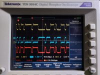
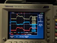
I see a lot of high frequency component in your trace which is my main interest. I will be following Garmin’s guidance- what makes this fun for me is understanding what I’m seeing. Thanks for forwarding the link!Moving from theory and datasheet to reality, I decided to actually look at the CAN bus in my plane. I have the typical 22 gauge Tefcel twisted shielded pair wiring, not the special CAN bus stuff, and darn close to the 66 foot limit. I hooked the scope up at the AHARS, which is somewhere in the middle of the bus. Here are some pictures of CAN HI, CAN Lo, and the difference in red. While there are some edge artifacts indicative of reflection components, they are minimal, and noise is really minor. Looks like rise times are in the 66 to 72 ish nS and fall times are 140 to 142 nS. Pulse times are 1 uS and Hi and Lo signals are 1V each. Looks easily clean enough to have no problems. Also measured the twisted pair and determined its impedance is about 67 ohms, and prop delay is 1.57nS/foot.
So, given these rise and fall times and the prop delay of this cable, you can see how Garmin says around 66 feet max, as with the worst case transmitter to receiver delay/distance, the the impedance mismatch reflections end up pretty much absorbed in the slow rise and fall times.
Reinhard Metz
So, given these rise and fall times and the prop delay of this cable, you can see how Garmin says around 66 feet max, as with the worst case transmitter to receiver delay/distance, the the impedance mismatch reflections end up pretty much absorbed in the slow rise and fall times.
Reinhard Metz
Attachments
Pilot8
Well Known Member
Moving from theory and datasheet to reality, I decided to actually look at the CAN bus in my plane. I have the typical 22 gauge Tefcel twisted shielded pair wiring, not the special CAN bus stuff, and darn close to the 66 foot limit. I hooked the scope up at the AHARS, which is somewhere in the middle of the bus. Here are some pictures of CAN HI, CAN Lo, and the difference in red. While there are some edge artifacts indicative of reflection components, they are minimal, and noise is really minor. Looks like rise times are in the 66 to 72 ish nS and fall times are 140 to 142 nS. Pulse times are 1 uS and Hi and Lo signals are 1V each. Looks easily clean enough to have no problems. Also measured the twisted pair and determined its impedance is about 67 ohms, and prop delay is 1.57nS/foot.
So, given these rise and fall times and the prop delay of this cable, you can see how Garmin says around 66 feet max, as with the worst case transmitter to receiver delay/distance, the the impedance mismatch reflections end up pretty much absorbed in the slow rise and fall times.
Reinhard Metz
Reinhard
Great traces, thanks! The signals look very clean using the 27500 cable, in fact very encouraging given what I've been hearing. I've been trying to cut through the chaff so your info is very helpful. How many LRUs are on your CAN bus? Which method did you use to get the 67 ohm cable impedance? It sounds like Garmin is operating at 1Mhz; I wasn't able to get even that from tech support. Nice job on a clean looking bus!
I have 14 LRUs. I used two separate methods to determine the impedance: 1) Fed a long (measured also for the prop. delay calculation) piece of the cable with 2nS differential pulses (From Tek 250MHz pulse generator) on one end and terminated with a variable resistor on the other end. With the scope on the terminated end, varied resistor to best, no steps clean waveform, and then measured the resistor. (won't get perfectly clean because the driving end is 50 ohms from the generator); 2) measured the open circuit (at far end) capacitance and the closed circuit inductance of the cable. Z= SQRT(L/C). Both were close.Reinhard
Great traces, thanks! The signals look very clean using the 27500 cable, in fact very encouraging given what I've been hearing. I've been trying to cut through the chaff so your info is very helpful. How many LRUs are on your CAN bus? Which method did you use to get the 67 ohm cable impedance? It sounds like Garmin is operating at 1Mhz; I wasn't able to get even that from tech support. Nice job on a clean looking bus!
2nS Rise time pulses, not 2 nS pulsesI have 14 LRUs. I used two separate methods to determine the impedance: 1) Fed a long (measured also for the prop. delay calculation) piece of the cable with 2nS differential pulses (From Tek 250MHz pulse generator) on one end and terminated with a variable resistor on the other end. With the scope on the terminated end, varied resistor to best, no steps clean waveform, and then measured the resistor. (won't get perfectly clean because the driving end is 50 ohms from the generator); 2) measured the open circuit (at far end) capacitance and the closed circuit inductance of the cable. Z= SQRT(L/C). Both were close.
Pilot8
Well Known Member
I have 14 LRUs. I used two separate methods to determine the impedance: 1) Fed a long (measured also for the prop. delay calculation) piece of the cable with 2nS differential pulses (From Tek 250MHz pulse generator) on one end and terminated with a variable resistor on the other end. With the scope on the terminated end, varied resistor to best, no steps clean waveform, and then measured the resistor. (won't get perfectly clean because the driving end is 50 ohms from the generator); 2) measured the open circuit (at far end) capacitance and the closed circuit inductance of the cable. Z= SQRT(L/C). Both were clos
What did you get for capacitance per foot (or meter)?
I used an 86 foot piece and it was 3.29 x 10to-9 FWhat did you get for capacitance per foot (or meter)?
