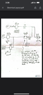
I’m updating the panel to glass and rewiring. Attached is the general layout. 5-6 yrs ago DanH advised to put and ANL fuse on the firewall side before the B-lead enters into the cockpit. I believe he said the reason was in case the B-lead would ever short out going through the FW, it would blow the fuse. I would like someone to confirm that after days of me looking at diagrams, pins, and connections of all the avionics, my brain is tired.
The ammeter shunt and 50A CB are inside the cockpit along with the elec bus.
I believe the 50A CB is located correctly in case it happens to fail the a/c battery will be able to power the elec bus short term. By having the elec bus connected to the A side of the shunt the system will know immediately when the alternator, ANL or CB has failed.