
Van's Air Force
You are using an out of date browser. It may not display this or other websites correctly.
You should upgrade or use an alternative browser.
You should upgrade or use an alternative browser.
Baffling clean up
- Thread starter Jeff Bost
- Start date

I redid all the baffle seals including the airbox intake thanks to DanH! All the baffle seals were original 2001 installs and were the reinforced rubber. I could see where they were not sealing and many looked wrong to start with. I was hitting 430 and climbing until I would pull power way back around 20” MAP and lower to under 500’/min. Also I was seeing 210 oil temps and climbing until pulling back power. After the replacement baffle seals with the red silicon and RTV in the gaps, I’m now seeing a maximum of 405 at 2500 RPM and 24” MAP – a huge difference. Oil temp isn’t going above 190 in climb. Cruise all under CHTs 365 or under (about 20 degree spread) and oil about 165. Super happy and this was all just old poorly sealing baffle seals!

Last edited:
After the replacement baffle seals with the red silicon and RTV in the gaps, I’m now seeing a maximum of 405 at 2500 RPM and 24” MAP – a huge difference. Oil temp isn’t going above 190 in climb. Cruise all under CHTs 365 or under (about 20 degree spread) and oil about 165. Super happy and this was all just old poorly sealing baffle seals!
Well done Paul.
There is further improvement available in two areas, if you wish.
Pressure in the Inlet is relatively high, something on the order of static pressure plus (ballpark) 70~90% of the available dynamic pressure, so sealing there is particularly important. Unfortunately, most RVs surveyed, including yours, have baffle rubber extending forward from the side and center walls. In most cases pressure pushes the seal away from any contact with the fiberglass cowl. Result is a large leak, often at both the inboard and outboard sides.

Study the inlet sealing in post #49. Note how the rubber strip across the bottom of the inlet extends upward on both sides. It's something like a "U" with a wide base. Also note it is fastened to the lower cowl, and overlaps the side baffle walls. Pressure pushes it against the side walls. A small sheet metal curved fillet improves the profile so the seal can lay in the corner.

Second improvement would be to install the rear, side, and front seal strips as one piece each, without any overlaps. Each overlap forms a leak area equal to the thickness of the seal material, extending an inch or more from the lap. It's the Catch 22 of silicone seals, as they tend to be thicker than the (miserable) black rubber reinforced seal material.
It's easy to coax unreinforced silicone strip into laying properly along convex curved baffles. Place all the pop rivet holes in the sheet metal. Starting at one end, place a single rivet to begin attaching the silicone. Now stretch the strip slightly, and hold it stretched while you drill through the strip at the next hole. Place the rivet, stretch, drill, repeat. The stretched silicone will naturally curve over and assume the correct shape. How curved can it be and still lay correctly? Here's a Kitfox firewall I did a few years ago. That upper baffle seal is far more curved than anything in the RV world:


Arguably, a builder may wish to put joints in the seal strips at junctions between metal sections, just to ease the job in the event the baffles need to come off for cylinder work. Personally I don't think it adds much work to drill out the soft aluminum pop rivets, but as my dear departed mom liked to say, "To each his own, said the lady who kissed the cow". You want joints in long seal strips? Fine, install them like this:

Jeff Bost
Member
Looks Great! Still working on mine….I redid all the baffle seals including the airbox intake thanks to DanH! All the baffle seals were original 2001 installs and were the reinforced rubber. I could see where they were not sealing and many looked wrong to start with. I was hitting 430 and climbing until I would pull power way back around 20” MAP and lower to under 500’/min. Also I was seeing 210 oil temps and climbing until pulling back power. After the replacement baffle seals with the red silicon and RTV in the gaps, I’m now seeing a maximum of 405 at 2500 RPM and 24” MAP – a huge difference. Oil temp isn’t going above 190 in climb. Cruise all under CHTs 365 or under (about 20 degree spread) and oil about 165. Super happy and this was all just old poorly sealing baffle seals!
View attachment 70404
Attachments
Excellent explanation in general, i will change my overlaps to but joints for now.Well done Paul.
There is further improvement available in two areas, if you wish.
Pressure in the Inlet is relatively high, something on the order of static pressure plus (ballpark) 70~90% of the available dynamic pressure, so sealing there is particularly important. Unfortunately, most RVs surveyed, including yours, have baffle rubber extending forward from the side and center walls. In most cases pressure pushes the seal away from any contact with the fiberglass cowl. Result is a large leak, often at both the inboard and outboard sides.
View attachment 70408
Study the inlet sealing in post #49. Note how the rubber strip across the bottom of the inlet extends upward on both sides. It's something like a "U" with a wide base. Also note it is fastened to the lower cowl, and overlaps the side baffle walls. Pressure pushes it against the side walls. A small sheet metal curved fillet improves the profile so the seal can lay in the corner.
View attachment 70409
Second improvement would be to install the rear, side, and front seal strips as one piece each, without any overlaps. Each overlap forms a leak area equal to the thickness of the seal material, extending an inch or more from the lap. It's the Catch 22 of silicone seals, as they tend to be thicker than the (miserable) black rubber reinforced seal material.
It's easy to coax unreinforced silicone strip into laying properly along convex curved baffles. Place all the pop rivet holes in the sheet metal. Starting at one end, place a single rivet to begin attaching the silicone. Now stretch the strip slightly, and hold it stretched while you drill through the strip at the next hole. Place the rivet, stretch, drill, repeat. The stretched silicone will naturally curve over and assume the correct shape. How curved can it be and still lay correctly? Here's a Kitfox firewall I did a few years ago. That upper baffle seal is far more curved than anything in the RV world:
View attachment 70411
View attachment 70412
Arguably, a builder may wish to put joints in the seal strips at junctions between metal sections, just to ease the job in the event the baffles need to come off for cylinder work. Personally I don't think it adds much work to drill out the soft aluminum pop rivets, but as my dear departed mom liked to say, "To each his own, said the lady who kissed the cow". You want joints in long seal strips? Fine, install them like this:
View attachment 70413
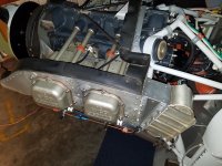
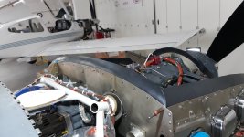
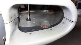
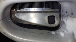
I can’t figure out what to change in the intake box based on the two pictures. Are you saying that the aft intake should be mounted forward, towards the prop? And what about the lower ramps? The black imagery of your intake are difficult to visualize.
Right now, I am using a hybrid of RV8 (my build) and RV14 in the intake area. I have the corner fillets with the seal coming aft from the lower side of the intake ramp. It seems that will seal up tightly. Where is the pressure originate in the “opportunities for improvement” to leak?
I guess I don't understand what you mean when you refer to the intake box or the aft intake. I believe that in Dan Horton's post & pics he was suggesting that the flexible baffling seals at the D-shaped cooling air inlets be relocated from being mounted on the engine baffles to being affixed to the lower half of the fiberglass cowling. That better allows the seals to push outward with airflow (and pressure) against the metal baffle components. The way the OP had their seals, incoming air might cause the flexible seals to curl open and create a large area for leaks.I can’t figure out what to change in the intake box based on the two pictures. Are you saying that the aft intake should be mounted forward, towards the prop? And what about the lower ramps? The black imagery of your intake are difficult to visualize.
Right now, I am using a hybrid of RV8 (my build) and RV14 in the intake area. I have the corner fillets with the seal coming aft from the lower side of the intake ramp. It seems that will seal up tightly. Where is the pressure originate in the “opportunities for improvement” to leak?
Not sure if that answers your question or not.
I am going to redo the baffle seals on my Rocket and I'm hoping you can provide more insight into how you managed the corners for the continuous piece. Is there a special technique? Did you use the 3/32" silicon?Can’t add much to the discussion except to double down on some key principles.
1. Anywhere air can get out and is not going through head fins or oil cooler is wrong. Perfection is desired here but rarely attained. You have a LOT of work to do to get to “acceptable”.
2. Baffle sealing to the cowl is significantly more difficult when you cut them into segments. Sometimes this is unavoidable but should be minimized to the maximum extent possible. I was able to stretch and form my side and rear baffles into shape on my Rocket with one continuous piece. These were silicone and were pretty compliant. yours have many overlaps and each one of those is a leak. It also appears that you have large segments that don’t even touch the cowl at all.
3. Not a showstopper, but a significant enhancement is the addition of the #3 and #2 “bypass ducts”. This addition makes a huge difference. Please do a forum search for plenty of hits on the subject.
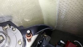
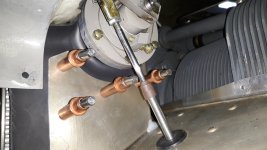
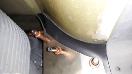
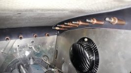
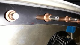
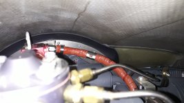
4. And a “hard STOP” on that governor line. Pictures suggest that the grommet is destroyed and you have metal to metal contact there. That’s a 400 PSI line and a leak is a very bad day. Nothing wrong with fabricating one, but you have to understand the engineering behind it. Whomever installed that one either does not understand or ignored. Both are bad.
Thanks!
sansoneservices
Well Known Member
Cowl it up and use a bore scope to inspect the baffle seals against the top cowlGuys,
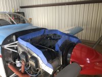
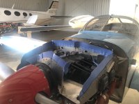
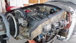
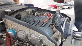
I’ve been experiencing high CHTs on 3 and 4 during cruise climb. Having to indicate 140 mph to have a chance at 400 F. I removed the top cowl this morning and snapped some pics of the baffling. Some old RTF around but I see the need for more. Big holes where the ignition harness comes through the rear. Any advice would be appreciated. I have a cockpit control for the oil cooler but it’s wired full open in the summer position. Some have suggest partially blocking the oil cooler if oil temp in acceptable. Thanks.
Jeff
Toobuilder
Well Known Member
Hi there. As I read this I hope I did not mislead you to thinking that I did the two sides and rear wall as a single continuous piece. To be clear, the back was one, and the sides were one (each). The join at the back corner was a standard overlap with some RTV strategically placed in a few gaps in the corners. That said, the curve following the top of the rear baffle was easy with a bit of stretching, and the front of the sides took a bit more effort to stretch into the general shape, then some minor trimming. Yes, the material was the 3/32 silicone roll from Spruce....I'm hoping you can provide more insight into how you managed the corners for the continuous piece....
Thank you. I would have been struggling trying to make those 90-degree corners with a continuous piece.Hi there. As I read this I hope I did not mislead you to thinking that I did the two sides and rear wall as a single continuous piece. To be clear, the back was one, and the sides were one (each). The join at the back corner was a standard overlap with some RTV strategically placed in a few gaps in the corners. That said, the curve following the top of the rear baffle was easy with a bit of stretching, and the front of the sides took a bit more effort to stretch into the general shape, then some minor trimming. Yes, the material was the 3/32 silicone roll from Spruce.
Another view to consider for anyone who might be hesitant to jump into maintenance.... Try not just "dropping it off and having it fixed." Try to find someone who can mentor you. It might be an A&P, or another builder. Just watch them work, then listening to there instruction, then trying to install a baffle seal yourself under there watch. I might open up a whole new world. Not all were born craftsman, but many of us are. If this is intreaging to you then that craftmam might be sleeping inside. So give it a shot and see how it feels. Then you get to buy tools!!! We can help with that too.
I do squared off corners with an overlap, then "stitch" with a couple pop rivets top-coated with RTV. keeps them rigid and sealed. As others mentioned, the curved bulkheads require some creativity to get them rolled inward as they curve around. I typically make a cardboard template which forms much like the baffle material, and when I'm happy with fit, transfer to the rubber.
Attachments
I'm almost done replacing the reinforced rubber seals with silicone using all the good advise I've read here. Thank you!
The flashlight leak test is looking good with very little gaps at the overlaps.. I filed down the edges on the overlapping material to minimize gaps.
EDIT: Thanks a lot DanH, your post #53 was very helpful!
The flashlight leak test is looking good with very little gaps at the overlaps.. I filed down the edges on the overlapping material to minimize gaps.
EDIT: Thanks a lot DanH, your post #53 was very helpful!
Attachments
-
 20250704_143822.jpg902.4 KB · Views: 190
 -
 20250704_143719.jpg1.3 MB · Views: 168
 -
 20250704_143808.jpg1.1 MB · Views: 146
 -
 20250702_184503.jpg828.1 KB · Views: 140
 -
 20250702_114535.jpg1,022.3 KB · Views: 123
 -
 20250702_114415.jpg1.3 MB · Views: 123
 -
 20250702_114344.jpg931.1 KB · Views: 127
 -
 20241218_192416.jpg1,022.7 KB · Views: 129
 -
 20241218_192443.jpg937.2 KB · Views: 166
 -
 20250708_190800.jpg1 MB · Views: 37
 -
 20250708_190808.jpg913.3 KB · Views: 36
 -
 20250702_183142.jpg888.7 KB · Views: 36
Last edited:
Dan,There is further improvement available in two areas, if you wish.
Jumping on your post from last year because my baffle seals could stand some improvement...
In the Kitfox example, it looks like you used silicone seal that's more narrow than the usual 3" material. What width would you recommend for an RV baffle seal to keep it pressed up/out against the cowl?
And how would you maneuver a singe piece of silicone seal along the side so it doesn't pucker at the tight downward bend on the baffles in front of cylinders 1 and 3?
Many thanks -
Dave
Required width is dependent on the trim of the aluminum baffle walls. Small gap, 2" width, larger gap, 3".
2" thin silicone can probably be made to follow the contour of the upper inlet ramps. Tough to do with 3" x 3/32" without gapping at the rear of the upper ramp, where it meets the cowl.
2" thin silicone can probably be made to follow the contour of the upper inlet ramps. Tough to do with 3" x 3/32" without gapping at the rear of the upper ramp, where it meets the cowl.
Guys,
I’ve been experiencing high CHTs on 3 and 4 during cruise climb. Having to indicate 140 mph to have a chance at 400 F. I removed the top cowl this morning and snapped some pics of the baffling. Some old RTF around but I see the need for more. Big holes where the ignition harness comes through the rear. Any advice would be appreciated. I have a cockpit control for the oil cooler but it’s wired full open in the summer position. Some have suggest partially blocking the oil cooler if oil temp in acceptable. Thanks.
Jeff
I'm almost done replacing the reinforced rubber seals with silicone using all the good advise I've read here. Thank you!
The flashlight leak test is looking good with very little gaps at the overlaps.. I filed down the edges on the overlapping material to minimize gaps.
EDIT: Thanks a lot DanH, your post #53 was very helpful!
Short feedback; I've noticed a significant improvement overall.
Interesting observation: I do have a push/pull controlled oil damper. The oil cooler gets air from the standard location above cylinder #6
Below are 2 screenshots from identical cruise pwr settings, but one pic is with the Oil Damper fully CLOSED and the other shows the Oil Damper fully OPEN.
Notice the diference in oil temp vs CHTs. The CHTs are approx 5 C higher with the Oil Damper fully OPEN (except #5 - seems unaffected)
-additionally the fully OPEN oil damper robs half a knot off the IAS.


Last edited:
