I'm pretty sure our engine guys have seen this one before, but I'd also bet most readers have not.
Did a leakdown on a 360 parallel valve, factory Lycoming, about 560 hours since new. Cylinders 1 and 3 were fine, 75/80 and 74/80. Go around the other side and "Uh oh!"


Yep, you're reading it right, 36/80 and 54/80, with lots of air blowing from the breather. Intake and exhaust were quiet. Definitely a ring seal problem here. Off with the jugs. Rings free and springy, grooves clean. Time for some cylinder measurements.
Lycoming says (SSP 1776-5) measure the cylinders for out-of-round at a point 4" from the bottom of the cylinder, in the plane of the valves and perpendicular. The max out-of-round is given as 0.0045".

However, a leakdown isn't done with the compression rings in the middle of the piston travel. We do it with the piston at TDC, i.e. rings at the top of the barrel. So, let's suspend a dial indicator just below the top of the ring travel and take diametrical measurements.
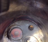
Largest diameter found, set the indicator to zero.

Problem found.


What we have is a pair of keyholed cylinders. The ring can't seal when the cylinder diameter is at max out-of-round at two points only 30 degrees apart.
Remember, the aluminum head is screwed and shrunk on to the steel barrel. Here the head is squeezing the top of the barrel into a shape that isn't round. The large diameter difference can be measured symmetrically on either side of the exhaust valve. Machining error, distortion of a complex casting, a combination? I don't know the exact reason, but it happens.
Did a leakdown on a 360 parallel valve, factory Lycoming, about 560 hours since new. Cylinders 1 and 3 were fine, 75/80 and 74/80. Go around the other side and "Uh oh!"
Yep, you're reading it right, 36/80 and 54/80, with lots of air blowing from the breather. Intake and exhaust were quiet. Definitely a ring seal problem here. Off with the jugs. Rings free and springy, grooves clean. Time for some cylinder measurements.
Lycoming says (SSP 1776-5) measure the cylinders for out-of-round at a point 4" from the bottom of the cylinder, in the plane of the valves and perpendicular. The max out-of-round is given as 0.0045".
However, a leakdown isn't done with the compression rings in the middle of the piston travel. We do it with the piston at TDC, i.e. rings at the top of the barrel. So, let's suspend a dial indicator just below the top of the ring travel and take diametrical measurements.
Largest diameter found, set the indicator to zero.
Problem found.
What we have is a pair of keyholed cylinders. The ring can't seal when the cylinder diameter is at max out-of-round at two points only 30 degrees apart.
Remember, the aluminum head is screwed and shrunk on to the steel barrel. Here the head is squeezing the top of the barrel into a shape that isn't round. The large diameter difference can be measured symmetrically on either side of the exhaust valve. Machining error, distortion of a complex casting, a combination? I don't know the exact reason, but it happens.
Last edited: