Van's Air Force

The definitive Van's Aircraft support community! Buying, building or flying an RV? Join our exclusive family of mentors and enthusiasts!

Multiple ground wires to a single location?

claycookiemonster

Well Known Member
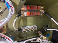
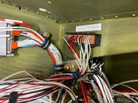
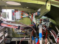
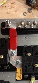
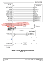
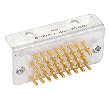
I have two grounding blocks (forest of tabs) just behind the instrument panel. Total of 40 tabs available. I also have many, many leads needing grounding. While I believe I have more tabs than leads needing to be grounded, it also seems like I could piggyback several leads onto a single tab to leave room for the future. What limitations might there be to doing this, other than making things crowded around the multi-lead tabs?
 
My professionally-built harness by a well known vendor has 2-3 ground leads to a single tab in many/most cases.
 
I think it’s personal preference up to a certain point. I wouldn’t jam three 16ga wires into a single crimp on a single connector. Also, some avionics devices have multiple, redundant ground pins. Wiring them into a single ground wire defeats the redundancy.

Personally, I stuck to: one ground, one tab. But I ended up using absolutely every tab so expanding my system will be difficult in the future. I’m willing to live with that.
 
Thanks all for your suggestions. FYI, I posed the same question to Stein's, who made my wiring harness. There is a bundle of black ground leads exiting from the harness. The answer from Stein was to go ahead and group the grounds as follows, "Yes, you can combine 2 or 3 wires per terminal as well. AWG22 I would combine 2 or 3 wires, AWG20 I would combine 1 or 2, and AWG18 or larger use one terminal each."
 
I have three grounding positions in my RV8, primarily for convenience. One in the avionics bay for everything avionics, electrical switches, comm. One in the engine bay for all the engine related grounding and sensors that are in the engine bay. I didn't want to run more wires through the firewalls. The last one is in the lower fuselage for other minor lighting because the wire runs are shorter and I was running out of tabs in the forest of tabs
 
Just remember what a ground loop is and how it's formed. All avionics grounds to one forest of tabs = very good idea. Lighting and DC motor circuit grounds = probably not critical as to loops.

Also do a mental FMEA: can I afford to lose X-many items if a single tab works loose/has a crimp failure.
 
Also, some avionics devices have multiple, redundant ground pins. Wiring them into a single ground wire defeats the redundancy.

Well that explains my GPS 175, wasn't sure why there were 2 power and 2 ground wires goin together must be for pinfail though because it shos them going to the same source
 

Attachments

  • 20230823_170258.png
    20230823_170258.png
    306.2 KB · Views: 116
Well that explains my GPS 175, wasn't sure why there were 2 power and 2 ground wires goin together must be for pinfail though because it shos them going to the same source
Either that or current-carrying capability of dual wires. I don't think a GPS navigator would draw that much, but a single D-sub pin is rated for a max of what - 8A?
 
Either that or current-carrying capability of dual wires. I don't think a GPS navigator would draw that much, but a single D-sub pin is rated for a max of what - 8A?

A regular D-sub pin can handle 5 amps. A high density is only 3.

It's pretty common for Garmin to have 2 power and ground pins for boxes that need more than 5 amps max because one pin can't handle that whole load.
 
IMG_0722.pngClay
You can make more busses for the grounds this way. Out of the aeroconnection book.
IMG_0722.png
 
D-Sub connectors are good for 5A. I like using these, the ground block is physically strong, the pins are rated for 15A, they are gold plated for long life and reliable connections. And the mounting connector screws on.


They are expensive, but if you shop around you can get these for a reasonable price. And you must get a DMC AF8 crimper with the right positioner.

I don't like connecting multiple wires to one pin, unless it's something like a set of lights etc.

Much better to make it more reliable and easier to change out stuff in the future.

Don
 
A regular D-sub pin can handle 5 amps. A high density is only 3.

It's pretty common for Garmin to have 2 power and ground pins for boxes that need more than 5 amps max because one pin can't handle that whole load.
Learned something today. I always thought they were for redundancy, and that the Garmin units would draw power from either OR both. I’ll have to compare a few of my wiring diagrams with the Garmin manual. I wired several of my avionics using that assumption (one pin from the main bus, one from the backup bus, for example).
 
Learned something today. I always thought they were for redundancy, and that the Garmin units would draw power from either OR both. I’ll have to compare a few of my wiring diagrams with the Garmin manual. I wired several of my avionics using that assumption (one pin from the main bus, one from the backup bus, for example).
In my experience they will explicitly state in the installation manual when multiple diode-isolated power inputs are supported; if they don't, then there is only one power input. Typically it seems that the TSO CNI products (navigators, transponders, etc) only have a single power input, although they may use more than one connector pin due to current requirements.
 
On a related note, I think it is useful to label grounds. I put numbers on all my ground wires and have a spreadsheet matrix of those wires which maps to the forests of tabs. It took me and my intern a day and a half to do this. When a device stops working first thing you do is check power and grounds. Imagine finding a bad ground at a device but not knowing which of your 80 grounds is at the other end (loose spade connector for example).

Warm regards,
Thats one of the things that Stein didn't do on my recent built that it upsetting. Everything else is fully labeled
 
One thing to consider when adding additional ground wires to a ground block are these:

It basically can double the number of wires going to a forrest of tabs ground block without having to double up wires on one terminal.
 
I ended up making a ground block that is located near the panel in addition to my forest of tabs that is located on the firewall. I was afraid that I was going to run out of spots on my firewall ground block. I had a bunch of signals that I thought were not as critical or perhaps sensitive as some others that I added to this block. You will find that you might have switch grounds or the like that can be grouped onto the ground block.

I actually made a PCB that uses a DB9 to distribute the grounds. I have fastons that then connect to my main forest of tabs on the firewall. I even made mine so I could have redundant connections to the firewall ground block if I'm feeling paranoid.

I used something similar, but bought it from these guys: https://vx-aviation.com/AXIS.html

1763792836389.png
 
Wouldn’t you label them, so when a device is having troubles, you don’t have to remove 48 fastons to find the one from that device?

just in defense of Walt's comment - no you wouldn't label the grounds, a ground is a ground. It does not matter - if the device has a ground then that what counts, however you certainly need to know where the power wire is & where it goes to ;)
 
just in defense of Walt's comment - no you wouldn't label the grounds, a ground is a ground. It does not matter - if the device has a ground then that what counts, however you certainly need to know where the power wire is & where it goes to ;)
If it doesn’t have a ground, or worse, an intermittent ground?
 
Wouldn’t you label them, so when a device is having troubles, you don’t have to remove 48 fastons to find the one from that device?
Doubt I could find the right one regardless in a sea of fastons even if they were marked, quicker and easier to just run a new wire if needed.
We label wires so we know their function. I don't label power/ground wires at the LRU units either, their color code (red/blk) makes it obvious what their function is.
(Bad grounds are a result of poor workmanship and should not happen).
 
Last edited:
D-Sub connectors are good for 5A. I like using these, the ground block is physically strong, the pins are rated for 15A, they are gold plated for long life and reliable connections. And the mounting connector screws on.


.........
Don
I installed one of these grounding block connectors on my Husky firewall and they are very very robust. They have lot of contact area and there are pins for 16 through 24 gauge wire. Good screw down on the connector and practically no amount of vibration can loosen them up.
 
I used a copper bus bar , drilled and taped 4-40 .
All grounds are identified on my schematic. IMG_8130.jpegIMG_8128.jpeg
 
Can’t say I’ve ever seen a threaded copper bus bar, soft copper is typically not threaded, terminals will likely loosen over time .
Pretty inconsistent stripping length on the wires. Looks like various hardware was used which may cause corrosion.
 
Can’t say I’ve ever seen a threaded copper bus bar, soft copper is typically not threaded, terminals will likely loosen over time .
Pretty inconsistent stripping length on the wires. Looks like various hardware was used which may cause corrosion.
I’m guessing it was the Orange heat shrink that made the wire look off ? ( I removed the sharpie mark too 😎) IMG_8132.jpeg
 
I installed one of these grounding block connectors on my Husky firewall and they are very very robust. They have lot of contact area and there are pins for 16 through 24 gauge wire. Good screw down on the connector and practically no amount of vibration can loosen them up.
Just be sure to install the back shell with them (I’ve seen them without).
 
Just be sure to install the back shell with them (I’ve seen them without).
Well I'll be. I didn't realize there was a back shell available. I only used the plastic receptacle that mates up to the grounding block. You would think that ACS would provide the back shell and thumb screws. The ACS page Q&A (and ACS answers are notoriously flaky) states there is no back shell. So after your comment I did some digging and sure enough ACS is wrong again.

Here is what TE Connectivity shows in their literature:

ENG_CS_82003_M_SERIES_PIN_SOCKET_0608.jpg

So now I will go looking to procure one of what TE refers to as a housing.

ACS stuff:


10-05895.jpgYou wou
 
Last edited:
I went the mil-spec route and used AS81714 terminal junction blocks. I got most of them from eBay so I didn't pay anywhere near full price. I'm not a fan of tabbed/blade connectors as they take up a lot of space and they're really hard to remove without gashing my hand when they finally release (gloves help). The TJCs are available in different configurations, some with a grounding stud for a bus bar and others with various bussed arranagements which make a convenient way to splice multiple wires together for lighting, etc.

The last page of my schematic shows how I allocated the TJCs.


1763909992674.png
 

Attachments

Here are some pictures partway through the build, the wires aren't completely cleaned up yet. But it shows the ground block and the rail where the bussed modules are. For the grouind plate, I drilled holes in a copper plate, then had it tin plated from a local plating company.
-Bob
 

Attachments

  • IMG_4603m.JPG
    IMG_4603m.JPG
    485.8 KB · Views: 114
  • IMG_5564m.JPG
    IMG_5564m.JPG
    519.4 KB · Views: 114
  • IMG_5565m.JPG
    IMG_5565m.JPG
    557.4 KB · Views: 114
Here are some pictures partway
Bob Thanks, looks great.
A brilliant engineer in the Lancair community (he was integral in the first? EFIS for experimentals -Chelton) hated faston terminals and that rubbed off on me, for better or worse. So, I’m looking for alternatives to forest of tabs
 
Bob Thanks, looks great.
A brilliant engineer in the Lancair community (he was integral in the first? EFIS for experimentals -Chelton) hated faston terminals and that rubbed off on me, for better or worse. So, I’m looking for alternatives to forest of tabs
Consider barrier strips and ring terminals.
 
Weigh whatever you choose to use. I was going to use a terminal strip till I put it on the scales. Little bugger is heavy. I ended up with a double sided FOT on the firewall. Everything is grounded to the same bolt.
 
The idea of a buss bar (copper alloy) is great, except for the tapped threads in copper; that needs a split washer to keep the preload on the screws. Typically you'll use this with just holes, and then #6 screws go through the screws into one of the lugs on the CB (eg. Klixon 7277).

For a grounding buss bar, do can do the inverse: Obtain get a piece of copper tubing, flatten it out, cut it down to form a strip of whatever length and width you desire. On each end of the copper strip, drill a hole that matches the size of the mounting bolt you want to use (eg. 1/4" - AN4-5A).

Drill (#27) holes along the length of the strip, spaced to allow for #6 PIDG ring terminals. Using #6-1" screws, AN960-L washers, AN364 (the thin version of the AN365) nuts to attach the screws to the strip. Slide ring-terminals over the exposed screw threads. Finish the attachment with another washer+AN364.
 
Doubt I could find the right one regardless in a sea of fastons even if they were marked, quicker and easier to just run a new wire if needed.
We label wires so we know their function. I don't label power/ground wires at the LRU units either, their color code (red/blk) makes it obvious what their function is.
(Bad grounds are a result of poor workmanship and should not happen
Hmmm... By that measure, I suspect you don't have any insurance for your plane, as any accidents would be pilot error, and that should not happen.
 
Just be sure to install the back shell with them (I’ve seen them without)
Why would a back shell be necessary? I do think some strain relief is needed, but that could be done as part of the wire harness management.
 
AC 43.13-1B, Chapter 11 details grounding aircraft electrical systems. It is worth taking a look at. Usually, when we start wiring, we just find a ground and go.

There is really good guidance about ground circuits together and other things to consider.
 
For those that use raw copper for buss bars, it’s quite easy to plate them. Heat up with a small torch, take your favorite solder, and go at it.
This buss strap was done with standard rosin core solder. Eazy Peazy tin plating.
 

Attachments

  • IMG_0599.jpeg
    IMG_0599.jpeg
    426.3 KB · Views: 54
For those that use raw copper for buss bars, it’s quite easy to plate them. Heat up with a small torch, take your favorite solder, and go at it.
This buss strap was done with standard rosin core solder. Eazy Peazy tin plating.
Why do they need to be plated?
Just curious. I thought copper is a better conductor.
I didn't plate any of the bars I installed. I have a couple and one or two bridging switches for ground buss.

I labeled grounds.
 
Last edited:
Doubt I could find the right one regardless in a sea of fastons even if they were marked, quicker and easier to just run a new wire if needed.
We label wires so we know their function. I don't label power/ground wires at the LRU units either, their color code (red/blk) makes it obvious what their function is.
(Bad grounds are a result of poor workmanship and should not happen).
I still don't get it. Bad grounds may be the result of poor workmanship and should not happen, but that doesn't mean it doesn''t happen. Just label the darn wires and move on, even grounds. Sometimes it's not so easy to run another wire and certainly intermittent issues can be brutal to diagnose too . I'm all for saving time/effort, but just don't understand the benefit of avoiding such a small effort. What am I not getting?

Note: Nuclear/mechanical engineer here....which makes me just smart enough to be stupid with electrical.
 
Why do they need to be plated?
Just curious. I thought copper is a better conductor.
I didn't plate any of the bars I installed. I have a couple and one or two bridging switches for ground buss.

I labeled grounds.
They don’t necessarily. I have raw copper bar per Vans original set up that’s going on 20 years FWF and no issues, so far.
Tin plating reduces oxidation and inhibits corrosion technically extending the life of the copper. It reduces the chance of oxidation and corrosion under terminals.

Most of the wire we use is tin plated for this reason and for ease of soldering.

Builders choice. I was just pointing out it is easy to do, should you choose.
 
Back
Top