Rather than muck up the Carbon Fiber Wings thread (https://vansairforce.net/community/showthread.php?t=133700), I've started another here specific to combustion air intake.
Bob posted
https://vansairforce.net/community/showpost.php?p=1659550&postcount=153
I posted
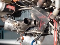
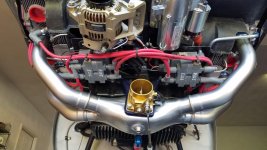
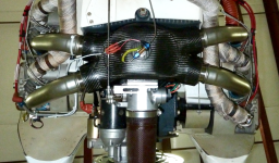
I had previous rigged pressure taps, primarily to look at the differential pressure across the nozzle bleeds on a constant flow fuel injection. The common belief was that pressure, assumed to be positive on the upper plenum side, could go negative, reducing or reversing the flow through the bleeds. There were two different experimental setups, one being a Big Picture view, and the other being a detail view, deltaP through a 720 degrees of crank rotation (0.05 sec at 2400 RPM) after the installation of turbo injector shrouds.
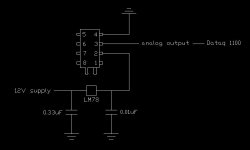
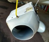
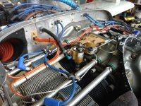
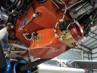
The Big Picture setup placed an aquarium bubble rock next to each injector nozzle, tapped into the top of the airbox, and tee'd into the manifold pressure line for the EIS. All the tubes led to the cockpit where I could connect a manometer as desired.
I've attached a data sheet. Line 17 was the test focus; average upper plenum pressure was always higher than average manifold pressure at the port, thus bleed air would be flowing as desired. No surprise here; the point was to determine how much. Not shown on this sheet but of equal interest, plenum pressure in the immediate vicinity of all nozzles was relatively even. That may not be true for all cowl setups.
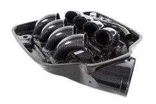
Line 18 is the measurement of interest in the context of Bob's Sky Dynamics manifold. The values on the sheet reflect an FM-200 on a stock Lycoming horizontal intake sump, the manifold on the M1B parallel valve as well as most IO-360 angle valve and 390A's. The pressure loss (manometer deltaP) between the airbox and the primer port measured 14.5 inches H2O at 2500 ft, with the loss being reduced with altitude gain. Since I already had a pretty good idea of the loss for the airbox and FM-200 (from AFP's flow bench), the loss in average pressure for the Lycoming parts works out to be about 9.5" under the given conditions. Pressure variation across two crank rotations (the detail view) is more interesting, but that's a subject for another thread.
Lines 22 through 25 was a different approach to the same question. Line 30 reflects on the accuracy of another spreadsheet for calculation of pressure recovery at the combustion air intake.
The 14.4" H2O loss is about an inch of manifold pressure (1.0592" Hg). A better manifold would minimize that loss. If the 23.3" Hg Bob reported is true, the SD manifold not only negates the loss, but boosts pressure at the port. It would be really, really interesting if true.
So, Bob, that's what I did, and after you finish all the wing testing, and if you too are curious, well, all it really takes is two pressure taps...go for it! And Steve, comments welcome.
Bob posted
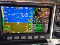
which caught my attention because 23.3" hg under those conditions would be really, really good. I asked Bob for more info, and being a generous soul, he shared much here:Cruise at 9500', WOT (23.3"), 2300 RPM, 12.4 gph (slightly LOP, 14.9-15.2 AFR), came in at 218 KTAS.
https://vansairforce.net/community/showpost.php?p=1659550&postcount=153
I posted
23.3" seems high for the conditions a few posts back. Breathing through a 3" inlet, at 9500, 54F, 230 RPM, 0.95 VE, and 218 KTAS, static pressure should be 20.98" with a pressure rise of 1.09", a total of 22.07" before the throttle body. Typically there would be some subsequent downstream loss for the intake plumbing (it's about an inch for my 390). Here, for 23.3 to be valid, the taper pipe manifold would have to be doing something interesting, perhaps due to increased velocity at the port (the taper), or better wave action, or both...an increase rather than a tract loss.
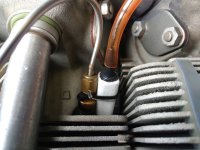
A differential manometer would tell. One static tap at the tube in front of the FM300, and one at a primer port, or better, an accumulator tapping several ports.
I had previous rigged pressure taps, primarily to look at the differential pressure across the nozzle bleeds on a constant flow fuel injection. The common belief was that pressure, assumed to be positive on the upper plenum side, could go negative, reducing or reversing the flow through the bleeds. There were two different experimental setups, one being a Big Picture view, and the other being a detail view, deltaP through a 720 degrees of crank rotation (0.05 sec at 2400 RPM) after the installation of turbo injector shrouds.
The Big Picture setup placed an aquarium bubble rock next to each injector nozzle, tapped into the top of the airbox, and tee'd into the manifold pressure line for the EIS. All the tubes led to the cockpit where I could connect a manometer as desired.
I've attached a data sheet. Line 17 was the test focus; average upper plenum pressure was always higher than average manifold pressure at the port, thus bleed air would be flowing as desired. No surprise here; the point was to determine how much. Not shown on this sheet but of equal interest, plenum pressure in the immediate vicinity of all nozzles was relatively even. That may not be true for all cowl setups.
Line 18 is the measurement of interest in the context of Bob's Sky Dynamics manifold. The values on the sheet reflect an FM-200 on a stock Lycoming horizontal intake sump, the manifold on the M1B parallel valve as well as most IO-360 angle valve and 390A's. The pressure loss (manometer deltaP) between the airbox and the primer port measured 14.5 inches H2O at 2500 ft, with the loss being reduced with altitude gain. Since I already had a pretty good idea of the loss for the airbox and FM-200 (from AFP's flow bench), the loss in average pressure for the Lycoming parts works out to be about 9.5" under the given conditions. Pressure variation across two crank rotations (the detail view) is more interesting, but that's a subject for another thread.
Lines 22 through 25 was a different approach to the same question. Line 30 reflects on the accuracy of another spreadsheet for calculation of pressure recovery at the combustion air intake.
The 14.4" H2O loss is about an inch of manifold pressure (1.0592" Hg). A better manifold would minimize that loss. If the 23.3" Hg Bob reported is true, the SD manifold not only negates the loss, but boosts pressure at the port. It would be really, really interesting if true.
So, Bob, that's what I did, and after you finish all the wing testing, and if you too are curious, well, all it really takes is two pressure taps...go for it! And Steve, comments welcome.
Attachments

Last edited:
")