Yep. The long, metal prop is a tuning fork and when combined with the firing frequency of the 4 cylinder will set up a resonance that can break the crank.
Break the prop.
The dynamic counterweights (in those certain models) takes care of that resonance.
Note pendulum absorbers are tuned to a specific
order rather than a
frequency.
The type of dampener discussed here is the alternate method of taming that resonance issue.
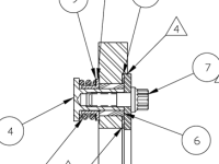
In this specific application, it's more likely simply acting as a flywheel mass, as its location near the node of the first torsional vibratory mode makes it largely ineffectual as a vibratory damping device.
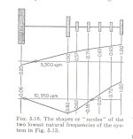
I've attached an illustration from DenHartog's
Mechanical Vibrations. It's a classical representation of mode shape for the two lowest natural frequencies. From left to right, it represents a large driven inertia, a flywheel inertia, four crank throw inertias, and the accessory inertias. The values are relative amplitudes of angular displacement (shaft twist), the maximum ("1") being found
at the free end of the system.
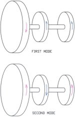
I've also attached a sketch in which I've lumped the crank and accessory inertias together. It illustrates one aspect of what the mode shape diagram is representing...the
direction of vibratory rotation when the system is being excited with a forcing frequency equal to one of these natural frequencies.
See the little circles where the plot lines cross the X axis? Those are the
vibratory nodes for the two modes of vibration. A node is a point along the chain of connecting stiffness members
where there is no angular displacement.
Now read carefully...if we have to equal inertias connected by a shaft, the node will be located precisely halfway between them, and the two inertias will oscillate with opposite and equal amplitude. If we connect two unequal inertias, the node will move toward the larger inertia, because the large inertia oscillates with proportionally less amplitude. If the large inertia is
much greater than the smaller, the node will be very close to the larger, as the larger acts almost like an immovable object.
That's what you see in the DenHartog figure, smaller inertias oscillating with far more angular displacement than the large inertia. The first mode has a node close to the large inertia, as the vibratory amplitude of the large inertia is only about one fifth as much (0.2) as the free end of the system. In the second mode, there are two nodes, one close to the large inertia and one somewhere along the crank. The node near the large inertia (the prop) is moved even closer to it, as the angular displacement of of the large inertia is tiny (0.06).
Here's the point...there is no angular displacement at a node, thus a viscous torsional damper located at a node is
useless. I have made no attempt to determine the precise location of the node for the first mode (or any other), but you can be sure it's quite close to the prop flange in the case of a Lycoming four banger connected to a propeller.
Compare with the typical auto engine application...the damper is at the free end of the system, the location with the greatest angular displacement. Same is true for the location of pendulum absorbers. Put them near the prop and they would be far less effective.
.


")