Van's Air Force
You are using an out of date browser. It may not display this or other websites correctly.
You should upgrade or use an alternative browser.
You should upgrade or use an alternative browser.
Archer Antenna Wingtip Install Questions
- Thread starter azflyer21
- Start date

Not flying yet, but...
I glassed the antenna strips to the inside of the wingtip. I screwed a clamp inside the antenna for the coax. Then I ran the coax along spanwise through the rib lightening holes, secured with Adel clamps. My wings were off, and in fact had a skin panel yet to be installed.
I glassed the antenna strips to the inside of the wingtip. I screwed a clamp inside the antenna for the coax. Then I ran the coax along spanwise through the rib lightening holes, secured with Adel clamps. My wings were off, and in fact had a skin panel yet to be installed.
I can sure use a little guidance on installing the Archer antenna in the wingtip.
-How did you mount the antenna?
-How is it connected to the coax?
-Once the wing is installed is it difficult to route the coax thru the fuselage?
Thanks!
Identify the "radiating leg" (diagonal piece, which then turns and runs back); the "ground leg" (straight piece parallel the the backwards running radiating leg); and the "feeder/matching network leg" (short diagonal piece, with a parallel capacitor built into it.
The ground leg needs to be mounted, physically and electrically, as close as possible to the end rib. Method (1): Before mounting nut plates to the wingtip (or remove them if already done), place the ground leg between the wing tip and the nut plates; match drill wingtip and antenna ground leg at all places. Rivet wingtip - ground leg- nut plate. Remove all paint from the wing under the attaching screws, so there is a good ground leg to wing metal to end rib electrical connection, at many places along the ground leg. Method (2): Rivet an "L" shaped piece of aluminum to the end rib, as long as the ground leg of the antenna. Rivet the ground leg to the L shaped aluminum, at numerous points along the leg. I oriented this stuff to put the leading edge of the antenna behind the landing and nav/strobe lights, and aft of the aluminum foil heat shielding - maybe 8" or so back from the front. All of the lighting wires ran well forward of the antenna. With method (1) the antenna comes of with the wingtip - I left enough slack in the coax so I flip the wingtip over onto the top of the wing. With method (2) the wingtip will stay on the wing when you remove the tip - probably a bit better.
Connecting coax: follow Archer instructions. Center conductor goes to the parallel plate capacitor (electrically dc isolated from everything); braid/shield goes further inboard on the matching leg, to the piece that is electrically connected to the ground leg.
I have a -10 so cannot comment on cable routing, but had no problem with the -10.
Photos here:https://turnerb14a.blogspot.com/2018/10/installed-archer-vorils-antenna-in.html
I used a solder sleeve to connect shielding to the antenna, some strips of glass/epoxy to stabilize the antenna. Since I have to run a cable all the way out to wingtip at a later date, I used a BNC connector at the wingtip and ran cable in fuselage with enough length to run out to wingtip. I followed instructions that came with antenna very closely, replaced some of the original wingtip nutplates after match-drilling holes to the antenna. If you don't have instructions, you can find them here: https://www.aircraftspruce.com/catalog/pdf/SA001.pdf
I used a solder sleeve to connect shielding to the antenna, some strips of glass/epoxy to stabilize the antenna. Since I have to run a cable all the way out to wingtip at a later date, I used a BNC connector at the wingtip and ran cable in fuselage with enough length to run out to wingtip. I followed instructions that came with antenna very closely, replaced some of the original wingtip nutplates after match-drilling holes to the antenna. If you don't have instructions, you can find them here: https://www.aircraftspruce.com/catalog/pdf/SA001.pdf
Last edited:
+1 for a good ground
Like Bob mentioned, a good ground is key and having the full length of the antenna base leg sandwiched with the nutplates makes that happen. I attached the other legs of the antenna to the inner wingtip surface using several Clickbond base screws as well as installing a WDG clamp for the coax cable to a Clckbond screw. https://www.aircraftspruce.com/catalog/hapages/clickbondstuds.php?clickkey=9826
Routinely get 120nm plus lock on any VOR.
The ground leg needs to be mounted, physically and electrically, as close as possible to the end rib. Method (1): Before mounting nut plates to the wingtip (or remove them if already done), place the ground leg between the wing tip and the nut plates; match drill wingtip and antenna ground leg at all places. Rivet wingtip - ground leg- nut plate. Remove all paint from the wing under the attaching screws, so there is a good ground leg to wing metal to end rib electrical connection, at many places along the ground leg.
Like Bob mentioned, a good ground is key and having the full length of the antenna base leg sandwiched with the nutplates makes that happen. I attached the other legs of the antenna to the inner wingtip surface using several Clickbond base screws as well as installing a WDG clamp for the coax cable to a Clckbond screw. https://www.aircraftspruce.com/catalog/hapages/clickbondstuds.php?clickkey=9826
Routinely get 120nm plus lock on any VOR.
Sam Buchanan
been here awhile
I can sure use a little guidance on installing the Archer antenna in the wingtip.
-How did you mount the antenna?
-How is it connected to the coax?
-Once the wing is installed is it difficult to route the coax thru the fuselage?
Thanks!
This is my RV-6 installation from many years ago but maybe it will give you some ideas:
http://home.hiwaay.net/~sbuc/journal/sportcraft.htm
I know it has been a couple of years since this topic was raised, but if anyone has an answer or an opinion I would like to hear it to this question: Can I put a BNC connection in the coax at the wing root and get acceptable performance. I would like to treat the coax like the other electrical systems and use connectors at the wing root.
Sure thing, you should be able to do that at the wing root. You just want to avoid changing the connection to the antenna itself where the coax splits out to the center conductor and shield connections, which it doesn't look like you want to do.I know it has been a couple of years since this topic was raised, but if anyone has an answer or an opinion I would like to hear it to this question: Can I put a BNC connection in the coax at the wing root and get acceptable performance. I would like to treat the coax like the other electrical systems and use connectors at the wing root.
Connectors do add a very small bit of signal loss (0.1 dB for my fellow EE nerds), but you'll never notice it.
HTH
Dave
Last edited:
I am planning on using hinges to mount my wingtips. Doing this I would plan on putting the ground leg of the antenna under the hing on the wingtip. I am thinking that will give me enough contact with the wing via the other half of the hinge being riveted to the wind and the hinge pin tying the two halves together… surely someone has done this and can tell me if it works well or not…
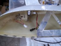
Here's mine. Directly attached to the nut plate for ground and double sided tape on the long edge
Routing coax was a paint becasue my plane didn't come with a conduit so it was pushing it through a bunch of grommets through the access panel but isn't supposed to be that hard. I used 25ft of RG400. There was maybe 2-3 foot extra. Connectors at the tip so the wingtip is removable.

Routing coax was a paint becasue my plane didn't come with a conduit so it was pushing it through a bunch of grommets through the access panel but isn't supposed to be that hard. I used 25ft of RG400. There was maybe 2-3 foot extra. Connectors at the tip so the wingtip is removable.
I’ve had an archer in a 7 and a 10 both with hinges.
On the 7 I spent a long time debugging it early on. The problem ended up being a poor quality crimp in the inline BNC at the wingtip. Going forward the performance was certainly acceptable for ILS/LOC but I wouldn’t get more than say 30nm on the VOR.
Fast forward 15y and the 10 was worse with the same setup. So I removed the inline BNC and riveted the antenna to the outboard rib. Now I’ll get 80+nm at 8000’. Was it the extra connector or the hinge?
Connections in general are by far the biggest cause of gremlins I’ve seen.
I see little point in having wing root connectors unless you are planning to land in a paddock someday and truck it out. Just coil everything up at the fuselage while building and then route/terminate at the hangar. Less work, less failure points.
Avoid hinges to mount the antenna. There was a previous post a while back and it doesn’t make a good ground connection because the hinges are anodized. This came up because the person who had mounted the antenna using hinges had poor reception.
I riveted a piece of angle on the antenna and then used screws and nut plates to attach to the rib. The other side has done split tubing held on with cable ties and just lays on the bottom of the wing tip. The install allows easy removal of both the tip and the antenna.
Regarding the use of a BNC connector, to put in perspective the previously mentioned loss of 0.1db, it would require a 3db loss to reduce the signal by 50%.
I used a BNC at the wing route. At the antenna end, it came with some RG400 that was split and attached to the antenna and a BNC. I removed that and split my RG400 and attached directly to the antenna.
Yeah, you can put a BNC connector in with minimal signal loss, if that's what you feel like you want to do. But I have to say, I don't get the desire to intentionally build in connectors at the wing root. Unless you end up in a hay field somewhere, most airplanes will never have the wings removed again. It seems like you're just asking for trouble with no real benefit.
I've worked with all manner of vehicles for a long time now. The majority of electrical gremlins and plumbing leaks happen at connectors, so as far as I'm, concerned, the fewer the better.
I've left enough service loop in all my wing wiring that in the unlikely event I have to pull the wings back off, I can cut the bundles and pitot/AOA lines at the wing root and then put connectors in after the fact. Currently there's very few mid-span connections in my airplane.
As far as the other questions being raised;
If you're riveting the antenna base leg to piano hinge, it seems to me that theres a good chance the ground will degrade over time. I suggest that it wouldn't be a bad idea to incorporate a ground strap between the two sides of your piano hinge.
A better option would be to skip that idea all together; Rivet a simple piece of aluminum angle to the outboard wing rib and rivet the antenna to that instead of your piano hinge. That would get you a rock solid ground plane and also allow you to remove the wingtip without having to deal with the coax to the antenna.
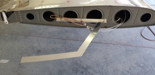
Yep - mounting like done in this photo is easy. The wingtip comes off, the antenna stays.
Note - I recommend you ignore the instructions to run you NAV/Strobe/LL wires along the leading edge of the antenna. Move the antenna aft to mid wing or so and gain some distance from this potential LED RFI source.
Note - This is a home brew antenna modified to extend the fore to aft element as far as possible into the wingtip. VOR ranges are 100+nmi.
Carl
Attachments