jliltd
Well Known Member
David,
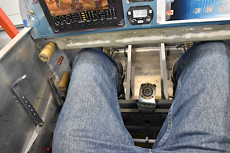
In my RV-3 any toggle switch along the bottom of the panel was primed for being inadvertently bumped while moving my hands around the cockpit. I had similar panel control placement such as yours where items in the center and right side, such as your com radio, iPad and clock, needed to be grasped, flipped or touched. While reaching around I was always unintentionally knocking toggle switches up or down. It was even more prevalent if I swapped hands on the stick to free up my right hand to twizzle or touch something on the panel, such as your iPad location. The hand coming off the stick is already low and near the bottom edge of the panel so after releasing the stick the upward movement of the hand was right at the bottom toggle location, as was the action of the other hand reaching to grab the stick. Remember the RV-3B is a personal rocket with the flight control location low and forward compared to the Cessna. It also does not have the panel setback or vertical spacing of Cessnas or even other RV models. You might want to mock up the stick in place and move it around while changing hands on the controls and then reaching towards the panel with the free hand. You might also be surprised how short the RV-3 control stick is and how close it crosses under the panel with little clearance. Mine only had about 1/8" clearance below the stock panel. You might have to cut down the stick even further for the switch panel.
Point being there is nothing fundamentally wrong with your current layout but focus on hand movement ergonomics and selector switch locations. You might want to run a towel-bar type switch bump guard below and maybe even above the switches. Think twin-engine mag switch guards. There are also individual switch bump guards that can be installed from the likes of Perehelion Designs.
I can't tell you how many times I bumped a switch while moving my hands around the RV3 cockpit. The master was the worst one to bump off. Thankfully I had a keyed ignition switch so never unintentionally switched off the mags. I would prefer ignition/mag switches be set off in a non-operating area since they are used during start and run-up and then mentally tucked away. Why not physically tuck them away too? Maybe locate them to a less valuable non-activity real estate area in lieu of, or in addition to a bump guard.
I would like to see some responses from other RV3 pilots with decent operational experience with their panel ergonomics and switches. All this could very well be "just me". I haven't had this type of issue in other model RV's. I only have an hour in an RV-4 which might have just as tight cockpit as the 3.
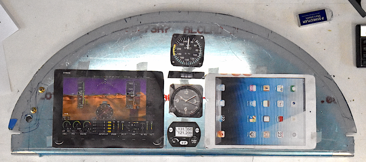
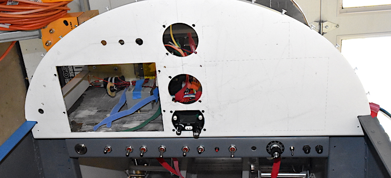
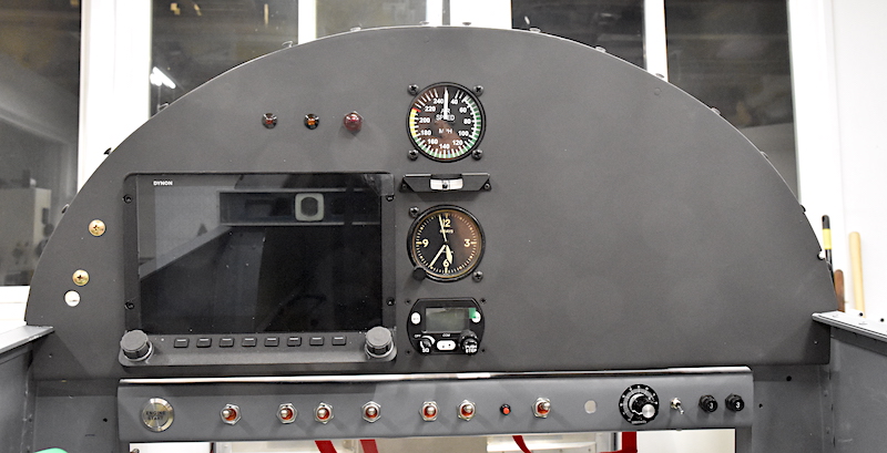
In your layout switches 2 thru 4 (from L to R) are fairly critical and #'s 3 & 4 right by the centered flight control stick are ripe for bumping. Especially with the comm radio controls in the same area. Have you considered moving the comm radio control head to above the Dynon EFIS (I am assuming something like a TY-91 or Dynon remote VHF com). Puts it where easily accessible by the left hand and in good view of the pilot. The EFIS and comm radio will probably get the most action in flight, followed by the right-hand accessed iPad.
I love keeping up with your project here. It's going to be an amazing bird.
In my RV-3 any toggle switch along the bottom of the panel was primed for being inadvertently bumped while moving my hands around the cockpit. I had similar panel control placement such as yours where items in the center and right side, such as your com radio, iPad and clock, needed to be grasped, flipped or touched. While reaching around I was always unintentionally knocking toggle switches up or down. It was even more prevalent if I swapped hands on the stick to free up my right hand to twizzle or touch something on the panel, such as your iPad location. The hand coming off the stick is already low and near the bottom edge of the panel so after releasing the stick the upward movement of the hand was right at the bottom toggle location, as was the action of the other hand reaching to grab the stick. Remember the RV-3B is a personal rocket with the flight control location low and forward compared to the Cessna. It also does not have the panel setback or vertical spacing of Cessnas or even other RV models. You might want to mock up the stick in place and move it around while changing hands on the controls and then reaching towards the panel with the free hand. You might also be surprised how short the RV-3 control stick is and how close it crosses under the panel with little clearance. Mine only had about 1/8" clearance below the stock panel. You might have to cut down the stick even further for the switch panel.
Point being there is nothing fundamentally wrong with your current layout but focus on hand movement ergonomics and selector switch locations. You might want to run a towel-bar type switch bump guard below and maybe even above the switches. Think twin-engine mag switch guards. There are also individual switch bump guards that can be installed from the likes of Perehelion Designs.
I can't tell you how many times I bumped a switch while moving my hands around the RV3 cockpit. The master was the worst one to bump off. Thankfully I had a keyed ignition switch so never unintentionally switched off the mags. I would prefer ignition/mag switches be set off in a non-operating area since they are used during start and run-up and then mentally tucked away. Why not physically tuck them away too? Maybe locate them to a less valuable non-activity real estate area in lieu of, or in addition to a bump guard.
I would like to see some responses from other RV3 pilots with decent operational experience with their panel ergonomics and switches. All this could very well be "just me". I haven't had this type of issue in other model RV's. I only have an hour in an RV-4 which might have just as tight cockpit as the 3.
In your layout switches 2 thru 4 (from L to R) are fairly critical and #'s 3 & 4 right by the centered flight control stick are ripe for bumping. Especially with the comm radio controls in the same area. Have you considered moving the comm radio control head to above the Dynon EFIS (I am assuming something like a TY-91 or Dynon remote VHF com). Puts it where easily accessible by the left hand and in good view of the pilot. The EFIS and comm radio will probably get the most action in flight, followed by the right-hand accessed iPad.
I love keeping up with your project here. It's going to be an amazing bird.
Last edited:
")
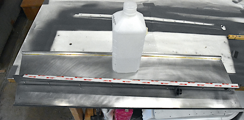


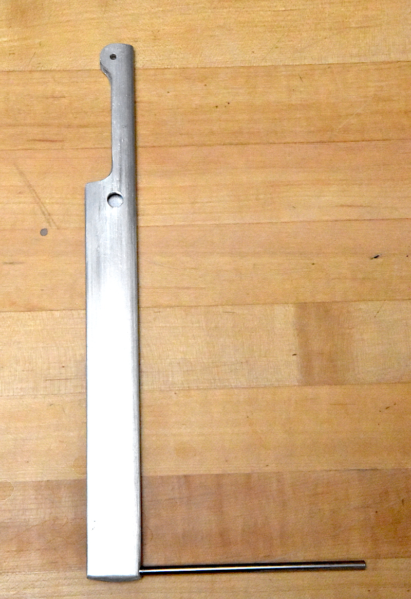
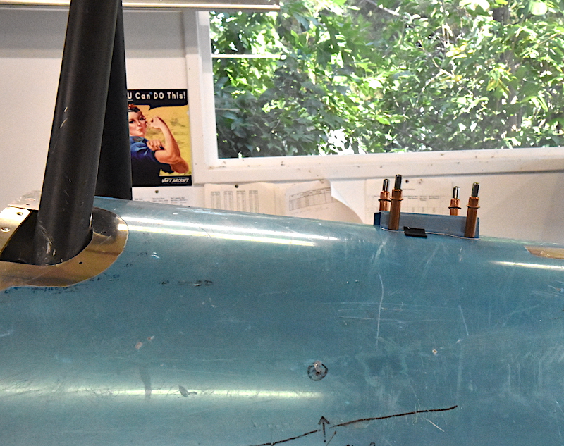
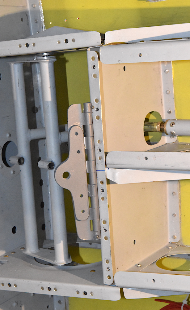
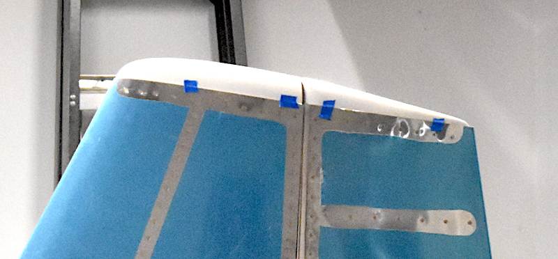
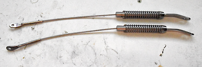
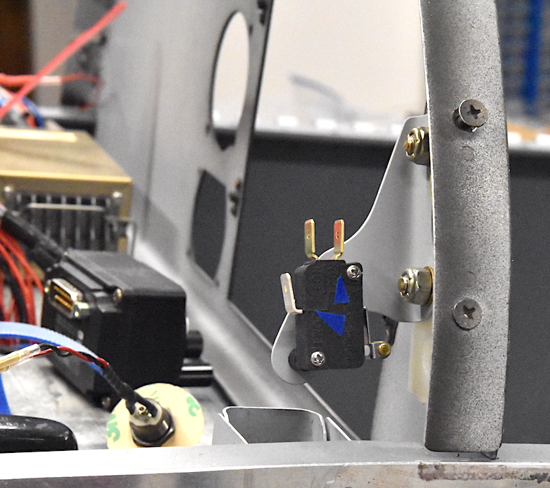
, Stall Warner.jpg")

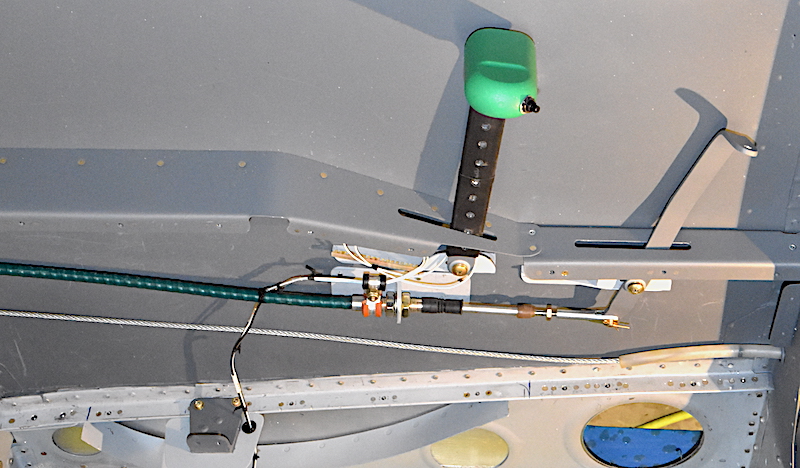


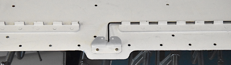
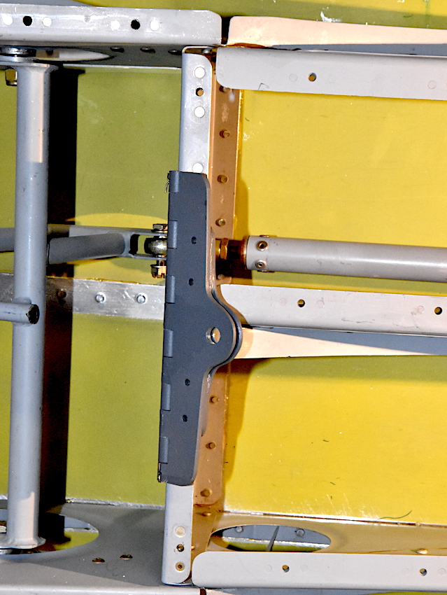
, Stall Warner Rev 1.jpg")