I’m doing some research on terminating the breather tube into the exhaust to burn off the oil like a smoke system would do and do a better job of keeping the belly clean.
After seeing it installed on another plane, I wanted to query the gallery.
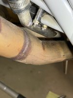
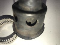
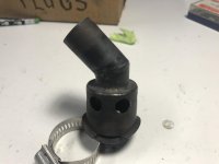
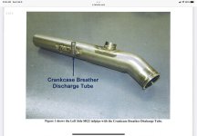
To install, an oval hole is made in the exhaust pipe to match the oval produced by cutting a 45 angle on a steel tube. The tube is ground to have a curve that matches the curvature on the exhaust pipe. Making sure there are no protrusions into the exhaust pipe and weld the tube to the exhaust to make a Y connection. A flex hose would then be used.
Install area would be determined after getting exhaust pipe in position and at least 12 inches from the end of the exhaust pipe.
I searched the forums and did not find anything other than complaints of dirty bellies and other ways to terminate a breather tube.
Has anyone done this or even considered doing? And is it a good or bad idea?
An interesting idea up for discussion.
After seeing it installed on another plane, I wanted to query the gallery.
To install, an oval hole is made in the exhaust pipe to match the oval produced by cutting a 45 angle on a steel tube. The tube is ground to have a curve that matches the curvature on the exhaust pipe. Making sure there are no protrusions into the exhaust pipe and weld the tube to the exhaust to make a Y connection. A flex hose would then be used.
Install area would be determined after getting exhaust pipe in position and at least 12 inches from the end of the exhaust pipe.
I searched the forums and did not find anything other than complaints of dirty bellies and other ways to terminate a breather tube.
Has anyone done this or even considered doing? And is it a good or bad idea?
An interesting idea up for discussion.
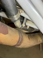
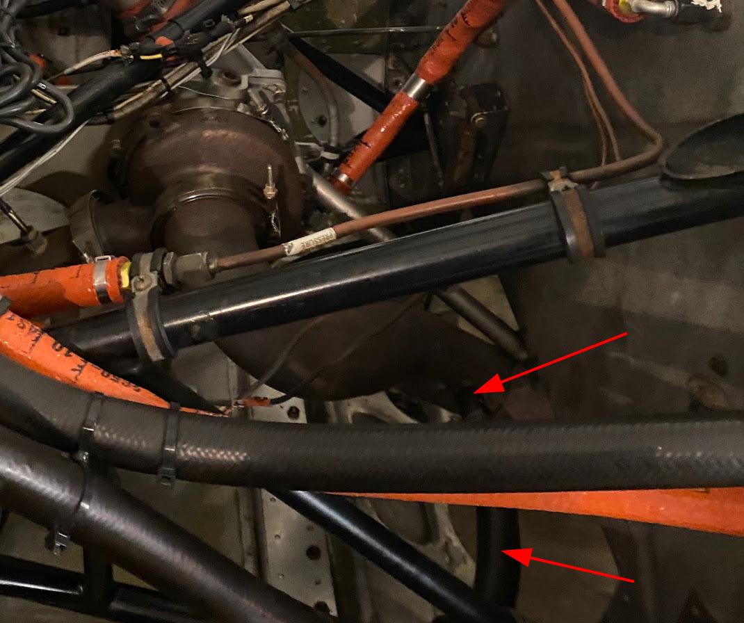
 It is oil residue from the fitting itself. After I saw that in the photograph I had to go out and wipe it off just to make sure myself!