Lemmingman
Well Known Member
Installing IO-360? Dont touch that firewall!
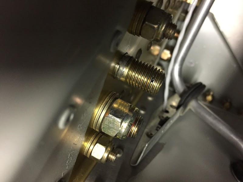
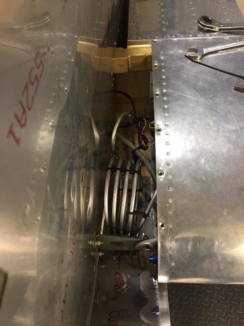
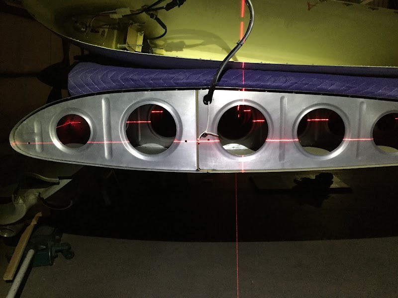
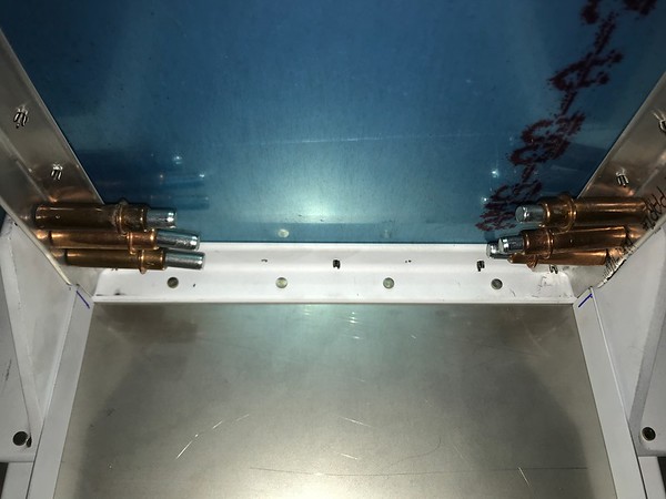
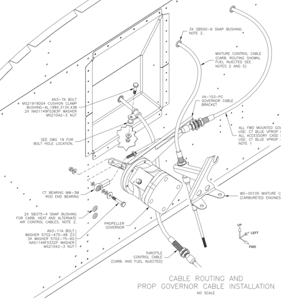
When you get to the point of drilling holes through your firewall you want to get a copy of OP32 which is an optional plans page for RV7. The default instructions will have you drill holes for a fuel pump and gascolator for a carbureted engine. The holes for the injected fuel system are in a different spot. The transducer manifold (VA168) also has some rivet holes in F-745 that are going to modified and may be easier while you're working on that forward structure. OP32 is available on the plans CD if you've got that. Otherwise, you may want to talk to Vans.
When you get to the point of drilling holes through your firewall you want to get a copy of OP32 which is an optional plans page for RV7. The default instructions will have you drill holes for a fuel pump and gascolator for a carbureted engine. The holes for the injected fuel system are in a different spot. The transducer manifold (VA168) also has some rivet holes in F-745 that are going to modified and may be easier while you're working on that forward structure. OP32 is available on the plans CD if you've got that. Otherwise, you may want to talk to Vans.
Last edited: