-POSTING RULES

-Advertise in here!
-
Today's Posts
|
Insert Pics
Keep VAF
Going
w/a Donation
VAF on Twitter:
@VansAirForceNet
|

12-18-2014, 10:09 AM
|
 |
Senior Curmudgeon
|
|
Join Date: Sep 2005
Location: Dayton Airpark, NV A34
Posts: 16,743
|
|
RV-7/7a Plan Gotcha's
Starting a thread.
Here is a link to a spreadsheet of gotcha's that may be useful.
Thanks to Allen for this.
https://docs.google.com/spreadsheets...QZg/edit#gid=0
__________________
Mike Starkey
VAF 909
Rv-10, N210LM.
Flying as of 12/4/2010
Phase 1 done, 2/4/2011 
Sold after 240+ wonderful hours of flight.
"Flying the airplane is more important than radioing your plight to a person on the ground incapable of understanding or doing anything about it."
Last edited by rv7boy : 12-06-2022 at 03:42 PM.
Reason: Changed spelling in title from "Gottcha's" for successful searches
|

12-18-2014, 03:41 PM
|
 |
|
|
Join Date: Oct 2005
Location: Estes Park, CO
Posts: 6,247
|
|
W414 DWG 10A
Awesome sauce. Thank you Mike. I'll kick it off.
When you build the W414 aileron hinge bracket. The plans call for flush head on the outboard side. Put them in the other way. Flush head on the inboard side. Otherwise the shop head can become a clearance problem.

__________________
Larry Larson
Estes Park, CO
E-mail: wirejock at yahoo dot com
Builder Blog: http://wirejockrv7a.blogspot.com
Donated 12/2022, plus a little extra.
RV-7A #73391, N511RV reserved
Disclaimer
I cannot be, nor will I be, held responsible if you try to do the same things I do and it does not work and/or causes you loss, injury, or even death in the process.
Last edited by Mike S : 12-18-2014 at 05:56 PM.
|

12-21-2014, 04:13 PM
|
 |
|
|
Join Date: May 2014
Location: Spring Hill, Florida; Flushing, Michigan
Posts: 114
|
|
R-606PP, R-902, R-405PD; DWG 7, Revision 5
There are factory punched holes not shown on the drawing. Read results of a call to Vans at the following link.
http://www.vansairforce.com/communit...d.php?t=120788
__________________
Karl Bambas
karl@bambas.com
1954 1st solo
1964 Mooney Statesman, 1979 C-172, 1948 Globe Swift (all sold)
RV-7 "Dream Weaver" N50KB
Empennage arrived 10/14
QB Wings & Fuselage arrived 06/15
Finish & FF kits arrived 11/15
Dual screen Garmin G3X instruments and harness delivered by Stein 01/16
First flight June 13th 2018
2023 Dues Paid
Builders Log
Family Blog
|

12-21-2014, 09:46 PM
|
 |
|
|
Join Date: Nov 2012
Location: SF Bay Area
Posts: 1,187
|
|
Quote:
Originally Posted by wirejock
Awesome sauce. Thank you Mike. I'll kick it off.
When you build the W414 aileron hinge bracket. The plans call for flush head on the outboard side. Put them in the other way. Flush head on the inboard side. Otherwise the shop head can become a clearance problem.

|
FYI ... from Sterling earlier in the year ...
The RV-7 Aileron brackets will both have the rivets flush on the outboard side of the assembly.
Sterling
On 9 Jan 2014 at 0:15, William Bencze wrote:
HI Vans, I'm putting together the outboard aileron brackets for my -7and have a question about which side to put the flush heads on ... It seems that the note from dwg 10A, W-413 assy was inadvertently duplicated for W-414 assy, implying that the flush heads of the AN426 rivets should be on the outboard side (text is the same as for W-413, including the call-outs for the W-413 components).It would seem that the flush heads should be on the inboard side of the W-414 assy to avoid any interference with the aileron after installation. See the red markup on the photo below. Which is the proper side?
Thanks much, Bill Bencze Builder 74152
__________________
Bill Bencze
RV-7, Flying 250+ hrs
VAF 2023 donation happily made
|

12-21-2014, 10:16 PM
|
 |
|
|
Join Date: Jul 2013
Location: US
Posts: 2,983
|
|
DWG 39 F-631D and C angles...very easy to misread the plans and make them wrong (e.g., backwards, upside down, what have you). Ask me how I know this.
|

12-25-2014, 10:44 AM
|
|
|
Join Date: Feb 2008
Location: Tucker GA
Posts: 190
|
|
W=414-L & R
Checking Dwg 9, the outboard end of the aileron leading edge skin has to clear the W-414-C angle and its protruding rivets, which are well inboard of the rivets back near the bearing, so would not expect the shop ends of these rivets to be a factor if on the inboard side, with the flush head on the outside. I'm hoping so, as mine are built per plans, but I'm not to the point of mounting the ailerons yet.
__________________
OldSam 
RV7A, Empennage, Wings & Tanks complete
Fuse under way
|

01-06-2015, 01:33 AM
|
 |
|
|
Join Date: Sep 2010
Location: Saint-Jorioz, France.
Posts: 200
|
|
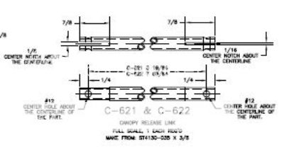
Tip Up Canopy release mechanism: C-621 and C-622
When building the Tip Up Canopy Release mechanism be careful at the C-621 and C-622 dimensions on drawing 47:
The length of both parts are shown between the holes and is not the total length as is usually the case elsewhere on the plans.
If you make these dimensions the total length you will end up 1 inch short.
Don't ask me how I know... It seems I'm not the only one to have done this mistake.
Alain.
__________________
Location: France
RV7 (F-PRVZ), Tip Up, Aerosport IO-375, Dynon Skyview, VP-X, Day VFR.
Flying since June 2017.
|

01-06-2015, 05:09 AM
|
|
|
Join Date: Jan 2011
Location: Cumming, Georgia
Posts: 917
|
|
If your building a 7 with a quick build fuselage.
One day I was sitting on a stool and wondering what the single hole was near the trailing edge of the wing on the fuselage.
I looked everywhere. Then found out it was an index hole for the step installation... This bugged me for a couple of days.
Jack
__________________
Smilin' Jack & Anita Hunt
N507H RV7, KJZP Jasper, GA
EAA690
APRS/ WB4JKY
Retired Corporate Pilot CFI-AI, MEL
CE500, LRJT, HS25, C650, SBJT, CL60
Hunt Aviation, LLC.
Pilot Service, IPC's Biennials.
Comm Glider
Last edited by Smilin' Jack : 01-06-2015 at 05:11 AM.
|

01-06-2015, 05:19 AM
|
|
|
Join Date: Oct 2011
Location: Kansas
Posts: 337
|
|
W-716 Pushrods
Don't trust the dimensions shown on the plans as they may end up being too short for some builds. Even though they are given in 1/32's! If you want to build these before fitting the wings to the fuselage then finish the wing end and cut the tubes longer than shown (search the threads for recommended extra lengths) and finish the fuse end later. Otherwise, you might be ordering more pushrod tubes and/or rod ends.
Some fit as shown, but others end up too short. No good answer as to why except that these are all built a little different despite match drilled parts.
__________________
Jim
Lenexa, KS
RV-7A
|

01-10-2015, 11:52 AM
|
|
|
Join Date: Feb 2008
Location: Tucker GA
Posts: 190
|
|
Tip Up Canopy release mechanism: C-621 and C-622
It is correct that the standard practice in dimensioning a part such as this is to show the furthest dimension from the part as an overall, with shorter dimensions running "inside", or closer to the part, from there. The exception is when the interior dimension is more critical than the overall, which appears to be the case here. If the part was dimensioned overall, with holes dimensioned 1/4" from the end, the error in the actual distance between the holes could be off by as much as the sum of three measuring, marking, and cutting/drilling operation errors, instead of one. It is likely, but not guaranteed, that some of the 3 possible errors would partially cancel each other out, but no need to take the chance.
__________________
OldSam 
RV7A, Empennage, Wings & Tanks complete
Fuse under way
|
Thread Tools |
Search this Thread |
|
|
Display Modes |
Linear Mode
|
Posting Rules
|
You may not post new threads
You may not post replies
You may not post attachments
You may not edit your posts
HTML code is Off
|
|
|
All times are GMT -6. The time now is 05:49 PM.
|