What's new
Van's Air Force

Don't miss anything! Register now for full access to the definitive RV support community.

Tip: Screwless Spinner

Tomas J

Active Member
Hi All,
It is time for me to mount the spinner.
I have seen this about screwless spinner...
http://mstewart.net/super8/spinner/index.htm
...and wonder if others have experience of it. It looks nice, but I see two risks with this method. The new layers of fiberglass separates from the plastic of the spinner, or the screws come loose, but you do not see it - in both cases, there is a risk of losing the spinner in the air. What do you think...?
If I make an ordinary mounting of the spinner... what kind of screws is the best to use?
 
I have it (the "screwless" one) and it looks great.. love it.. I check it before each flight and make sure it's not wobbly... I don't see a reason why the fiberglass would delaminate there... Follow correct procedures for fiberglass application and it should stay on there...
 
A local builder named Alfio who posts on this forum did his own screwless spinner and did a very nice job.
 
It looks nice, but I see two risks with this method. The new layers of fiberglass separates from the plastic of the spinner, or the screws come loose, but you do not see it - in both cases, there is a risk of losing the spinner in the air. What do you think...?

I'm not concerned about screws backing out of nutplates, but there is a definite risk of flange separation. Honestly measure your fiberglass fabrication skills before attempting this modification. For sure the flange requires craftsmanship. Even with good work nobody can offer a guarantee.

A key detail...composites are always weak in peel. In this case centrifugal force results in a peel load at the flange-to-shell joint. In addition, a glass fabric layup cannot be laid into a sharp 90 degree corner; some radius is necessary.

Both issues should be addressed by installing a flox fillet prior to the flange layup. Here the backplate is covered with red tape and waxed. You can see the white flox fillet. Just wipe it in with your fingertip......

Spinner%20Flox%20Filet.jpg


Cross section:

scan0004.jpg


.......then install the flange layup while the flox fillet is wet. Be sure to remove any air bubbles trapped between fabric and flox or between fabric plies.

EDIT (circa 2021): Tom's method for his Lancair (later in this thread), forming a flange as a separate component in a machined mold, is probably superior from mechanical design standpoint. That said, this flange, formed in place, is doing fine at 950 hours.

Yeah, it looks nice. Just remember....do it right or don't do it.

P8020002.JPG
 
Last edited:
Front bulkhead

I take it that there is no mechanical connection of the spinner to the front bulkhead.

LarryT

I'm not concerned about screws backing out of nutplates, but there is a definite risk of flange separation. Honestly measure your fiberglass fabrication skills before attempting this modification. For sure the flange requires craftsmanship. Even with good work nobody can offer a guarantee.

A key detail...composites are always weak in peel. In this case centrifugal force results in a peel load at the flange-to-shell joint. In addition, a glass fabric layup cannot be laid into a sharp 90 degree corner; some radius is necessary.

Both issues should be addressed by installing a flox fillet prior to the flange layup. Here the backplate is covered with red tape and waxed. You can see the white flox fillet. Just wipe it in with your fingertip......


Cross section:


.......then install the flange layup while the flox fillet is wet. Be sure to remove any air bubbles trapped between fabric and flox or between fabric plies.

Yeah, it looks nice. Just remember....do it right or don't do it.

 
I take it that there is no mechanical connection of the spinner to the front bulkhead. LarryT

No mechanical connection, just a very thin proseal surface pad, formed in place. The idea is to make it chafe-proof with zero freeplay. I bonded to the front bulkhead flange and used mold release on a semi-finished inner surface of the spinner. That allowed trimming all excess for best balance; no proseal blobs.

Prosealed%20Bulkhead.jpg
 
Last edited:

This looks *really* nice...I'm considering doing this. One question...how are the small "filler" pieces behind the prop held in (I assume platenuts on the back, of course...I'm asking about the "tabs" at the forward end...how are they secured to keep centrifugal force from making them flex outward)?

TIA

Steve
 
Neither tab is cantilevered as much as it may appear from the outside. One is very short. The other has a support flange tucked under the spinner shell....and probably doesn't need it.

Usual caution: experimental.

 
I do it the usual way

Thanks Dan for confirming my concerns about fiberglass ... I do it the usual way with tinnerman washers. I intend to use no scruves on front bulkhead, just remove the gap with proseal. Do I understand you right, that you put proseal on the front bulkhead instead of in the spinner.
 
I intend to use no scruves on front bulkhead, just remove the gap with proseal. Do I understand you right, that you put proseal on the front bulkhead instead of in the spinner.

Yes, PVA on the spinner and proseal applied to the front bulkhead flange. After cure you can pull the spinner and run a razor blade flush with the front and rear edges of the bulkhead, removing excess proseal squeeze-out.
 
Just laid up the fiberglass for my screwless spinner, looking good so far...used flox as above, etc. One quick question...

What size screws are people using on the spinner backplate-to-new fiberglass flange? #10-32 nutplates? Or smaller?

TIA

Steve
 
If I may make a suggestion.... I would definately suggest getting your prop dynamically balanced after adding this weight to the perimeter of the spinner :eek:
 
I used #8 screws... forgot how many.. maybe 5-6 on each half.. This was one of my favorite mods on the plane...
 
If I may make a suggestion.... I would definately suggest getting your prop dynamically balanced after adding this weight to the perimeter of the spinner :eek:

Thanks, Walt...yeah, I planned on that regardless, but definitely now that the spinner has had this touch of weight from fiberglass (and eventually screws and nutplates) added.
 
Looking good so far..next question (sorry for so many).

For the front bulkhead proseal on the flange, did you "finish" the inside of the spinner w/ paint first, then do the PVA on the inside of the spinner and the proseal on the bulkhead, or did you just use the bare interior of the spinner w/ PVA on it? I.e., would a layer of paint make enough of a difference that I should completely finish the inside of the spinner prior to this step? (I'm planning on finishing it if only to keep any grease or oil from soaking in to the fiberglass from the inside).

TIA again! This is turning out to be a fun diversion from engine stuff for a bit...

Steve
 
Steve, paint or no paint...the PVA won't care. I think by that point in the process I had sanded the interior smooth and may have done a light epoxy wipe. It was not painted until much later.
 
Steve, paint or no paint...the PVA won't care. I think by that point in the process I had sanded the interior smooth and may have done a light epoxy wipe. It was not painted until much later.

Thanks, Dan...by the way, I relied on your instructions for making the little filler tabs for the spinner and did some early test pieces...worked great! Your step-by-step was terrific. Now, to do the real deal with the flange and everything in place! Thanks!

Steve
 
But these also use screw, so where are the screwless spinners?

Joking aside, great work. A work of art I would say.
 
Photo

Neither tab is cantilevered as much as it may appear from the outside. One is very short. The other has a support flange tucked under the spinner shell....and probably doesn't need it.

Usual caution: experimental.

Hi Dan, Do you still have this photo or information about how you did this handy? Thanks! Mickey
 
Fiberglass skills

Thanks Dan. In the end I will probably take your advice and do this the standard way, since my fiberglass skills are currently very weak. I'll save this cool trick for the next project.
 
Another option

Hey Mickey. Good seeing you at OSH a few months ago.

There is another option to do a screwless spinner. I had to come up with one for an aluminum spinner since that is what I wanted. Dan's and the others look great, but that wasn't possible for an aluminum spinner. This idea will work for a fiberglass spinner too. I personally think this is a better way than the others, but I am bias since this was my idea.:D I have not seen this particular way done by anybody else, so maybe there is a reason why? It just comforts me more having aluminum/rivets holding this area together than fiberglass....but that's just me.

****DISCLAIMER: It has worked for me, but don't blindly do this without serious thought. I am not an engineer by trade, but have put a lot of thought and research into this design and chatted with many engineers/people before this was done. As Dan has mentioned (and everybody knows), there is some serious rotation/vibration going on at this location and the consequences of any problems could result in a very bad outcome very quickly. Sorry guys, I feel like this is one of those TV commercials with a drug that says all the bad things that can kill ya). ****

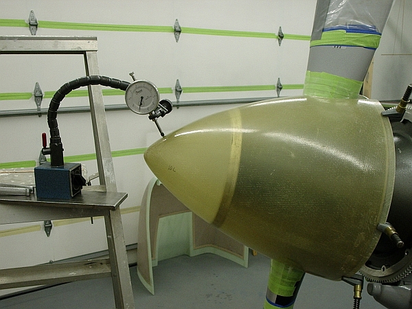
I had to make an adjustment from the smaller front spinner bulkhead fitting that was originally used (as you can see in the picture below), but once the other method (like what Dan used and McCauley Prop uses) was installed, I have had no issues (explained below). The forward/small bulkhead new design before this setup started off as minor, but could have been bad rather quickly.

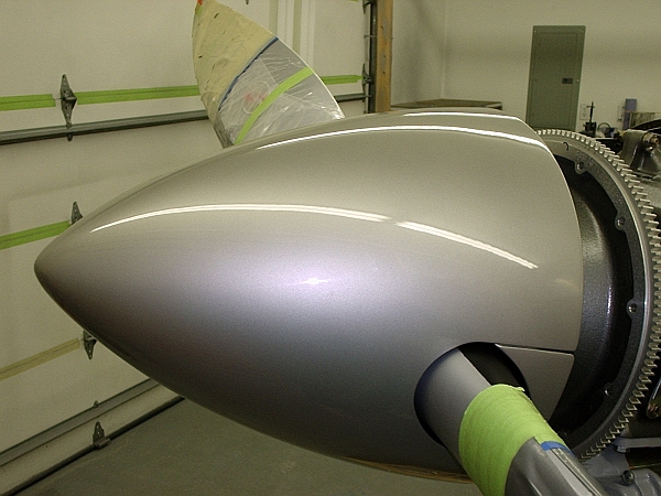
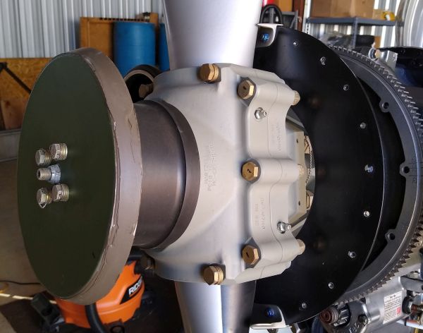
Here is a picture of the finished product. The only thing you can see are the rivets for the flange of the large bulkhead (better than screws on an aluminum one, at least if you are anal). If you are doing a fiberglass spinner, these can easily be covered with filler, microballons or whatever, and blended in very nicely.
2db1cas.jpg
[/IMG]

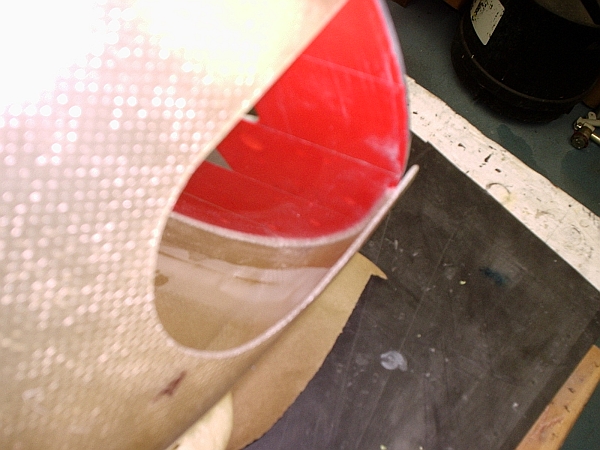
Basically, I took two large spinner bulkheads and cut them where there was as much overlap as possible (where the screws/nutplates held them together). I used #8 nutplates evenly spaced to hold the two overlapped pieces together and riveted the "ears" on the main bulkhead attached to the prop. To take the spinner off, I take the cowl off and unscrew the 12 screws holding the spinner (with the riveted bulkhead that was trimmed on the inside of the circle that has the nutplates on it). The other bulkhead remains attached to the prob, but is trimmed where the outside flange is taken away. You can see this in the pictures below.

A very big concern was making absolutely sure that everything was symmetrical and equal as far as cutting, trimming etc. My concern was having an imbalance like a tire and having issues with that.

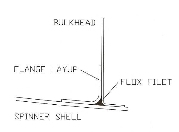
As far as the smaller inner bulkhead on the final product, I used a second one on that too. I Scotchwelded (super strong epoxy yet not quite as hard as JB Weld) just the flange or ring on the inside of the spinner. Then I used the normal small bulkhead so that flange is snug on the inside of the other flange. I Scotchwelded the void spots between the two flanges (with a release agent like packing take on one flange) so it would be a perfect snug fit. Obviously since the diameters are the same, it's not a perfect overlap from the geometry, but very good non-the-less. I'm sure this is not necessary to have the extra flange for protection/beefyness, but I like overdoing just in case.

The last thing to consider was the pressure required to keep the spinner snug on the two bulkheads (front and back) without too much pressure when the screws are tightened. I chatted with the engineers at McCauley to get their spec sheet on a prop/spinner configuration they use that is similar. I made the distance the same (can't quite remember but can look up in my notes), but I think it was 1/8" gap in a normal resting state. Then when I screw the 12 screws in, the gap closes and it's enough pressure to keep the spinner pulled into the small front bulkhead (since there are no screws physically attaching it).
2z6trax.jpg

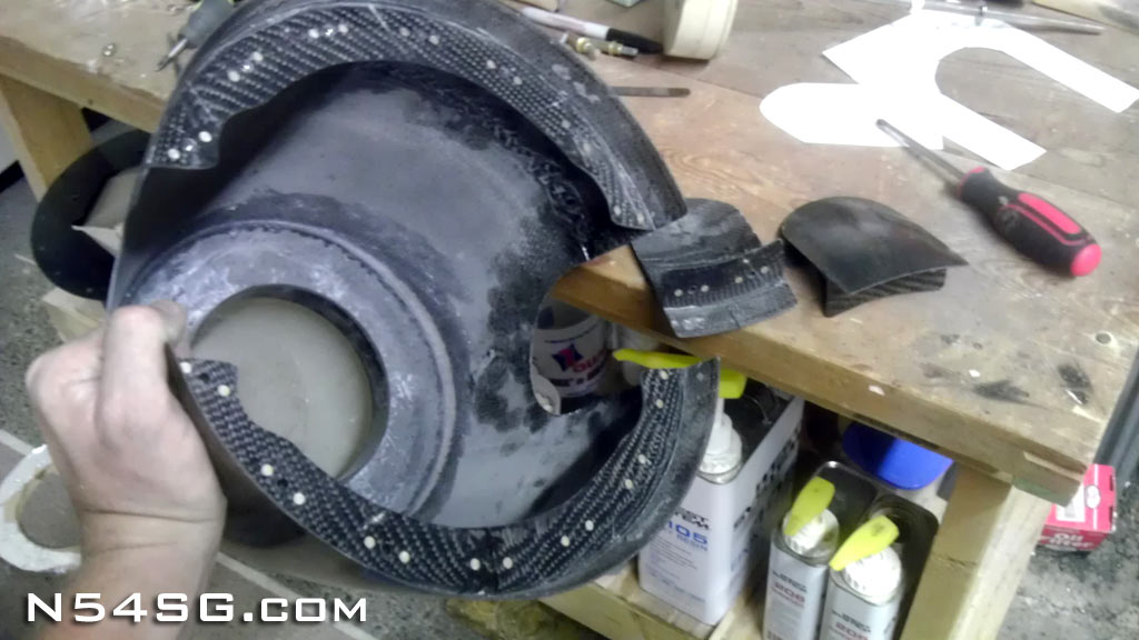
Please disregard the small forward bulkhead in this picture as this is the first version that had to be changed. Picture is to mainly show you the flange on the outer edge of the spinner and how it looks ready to be connected to the prop.
24xo2yp.jpg

This picture does not have the final mod to the spinner setup. It does not have the smaller forward spinner bulkhead/flange shown like I have now. Just pretend the aluminum cup looking thing on the end is replaced with the bulkhead and you'll have the idea.
2q1wkfm.jpg
 
Last edited:
Masterful

Hi Dave - good to "see" you again! Thanks for the writeup and photos - that is a very cool way to do the hidden spinner. I had to read it a couple of times to get it, but now that I do, it's really clever!
 
The third and fourth pictures are from the original install.

I had an aluminum "cup" on the end of the prop -- pic 4. The modified small forward bulkhead fitting (attached on the inside of the spinner -- pic 3) would slide over this cup for a very snug fit. Problem was with the vibration and rotation, the screws/bolts "sawed" into the delrin and aluminim to the point where the spinner would wobble a little. I could not tell from the cockpit, but a friend noticed it when I taxied by.

You can see in the third picture the chewing/sawing where the primer/aluminum is worn away near the screws.

This was a more involved process than it should have been. The next/final mod (as described above in the previous post) is by far the easiest and best way to go.

I probably didn't explain it too well (because I had to reread it several times too), but it's not that difficult to do and I think a very solid way to accomplish a screwless spinner.

Anybody please feel free to chime in to voice concerns with this system -- I have thick skin.
 
Last edited:
Quote:
Originally Posted by rv8ch View Post
Hi Dan, Do you still have this photo or information about how you did this handy? Thanks! Mickey

2r44idg.jpg


Can someone point me to Dans instructions for making these screw-less spinner filler tabs? I understand how the screw-less spinner is made in this post but not the tabs. Thanks
 
....but ImageShack and Tinypic both seem to have time limits, so some photos are missing. Anyone have a solution for that?

Picassa.............at least no missing images from them yet.

Or, Smug Mug, and pay a small fee but I understand they are there as long as you want them.
 
What's wrong with Picasa? 1gb or unlimited on plus and they don't disappear if not used frequently.
 
If your making a screwless spinner anyway, just make the flange all the way around the spinner before you cut the holes for the blades. Then, when the flange is cured, cut out your blade holes and Bingo, you have spacers with a flange to attach them!

Like this pic:
Blade_Spacers_02.jpg


This documents the entire screwless spinner project:
http://www.n54sg.com/spinner-and-bulkhead-overhual/

I have already cut out the holes for the blades but after seeing your pictures I realize all I need is a flange on the filler pieces just like the spinner. I can make the filler pieces out of the holes I cut out for the prop.

Thanks
 
If your making a screwless spinner anyway, just make the flange all the way around the spinner before you cut the holes for the blades. Then, when the flange is cured, cut out your blade holes and Bingo, you have spacers with a flange to attach them!


How do you first make sure the spinner is centered and not wobbling?

ETA: Aha...I read your blog and see how you did it (I used Dan H's method and it worked great, but I *really* liked your writeup...very impressive bit of engineering! Well done.. :) )
 
Last edited:
Back
Top