

pwprice
I'm New Here
Autopilot, servos, and installation kit purchased from Gulf Coast Avionics.
Wiring harness, pitot, and static connection purchased from Aircraft Spruce.
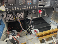
I just completed the installation of the Xcruze 100 in my VANS RV9A and am very pleased with the results. I connected the AP to my Garmin GNC250XL (circa 2003) from it’s secondary serial output and the ARINC A and B output. That connection only required three new pins in the J101 female 37 pin connector. The AP also requires connection the pitot and static systems. After working out a few bugs, the first flight was a delight. I put several waypoints in the Garmin nav/com route function. The AP acquired the GPS signal immediately and started monitoring my heading while taxing. Shortly after climb-out I changed the mode to GPS steering and the plane gently turned toward and intercepted the route. The AP anticipated each succeeding way point and gently turned the plane rounding each corner and fixing on the next waypoint heading. Climbs, descents, and heading adjustments are also easily make in the tracking mode.
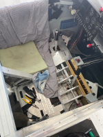
The installation was labor intensive removing all seats, interior panels, seat pans and several floor pans. After that routing the wiring was quite easy thanks to the excellent wiring harness from Aircraft Spruce. VANS provided excellent support about wire routing and allowable additional pass-through holes where required.
A few things, unnecessarily, made the install more difficult than needed.
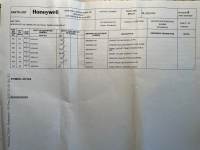
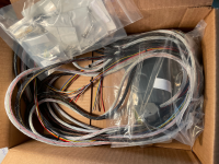
First, The Aircraft Spruce website has no description and no reviews for the $350 wiring harness. A customer support person at Aircraft Spruce willingly sent me a picture of the packing slip for the product. It said the harness was “30 inch” and included the 9 pin back shells for the servo connections but said nothing about the 25 pin connector needed for the autopilot control head. I ordered the wiring harness anyway and was more than pleasantly surprise. The wiring harness was 30 feet long and nicely separated into snake-skins for each servo. The remaining several wires, for mostly under the panel connections, were 5 feet long. The wires were all terminated perfectly into the 25 pin connector. Two other small annoyances were 1) the harness included exactly 16 female socket pins for making up the servo connections and none for the connection to the nav/com so if you don’t have a few of your own you cannot complete the wiring and 2) one of the servo connection back-shells is a 90 degree connection that proved worthless because it’s virtually impossible to connect it to the mounting screw holes in the servo. I used a straight connector that came with the autopilot itself and it worked fine. Overall, the product is excellent and I am glad I made the purchase.
Second, the installation kit specific to the RV9A cost $515 and included two small custom sheet metal mounting brackets and bunch of wire terminals that also came with the wiring harness and a bunch of installation diagrams but no instructions. The mounting brackets are essential and worked perfectly but if you’re handy with sheet metal you could make the same things for a few dollars.
Third, the wiring diagrams were incorrect for the RV9A. The pitch servo diagram has an option A and option B which makes the servo rotate either clockwise or counter-clockwise when commanded from the control unit. The Honeywell/BendixKing support people assured me the RV9A uses option A but they were wrong and the pitch responded opposite to my inputs during the ground test. The roll servo diagram does not include any model specific options but it also responded opposite during the ground test. Fortunately, the AP set up procedure lets you reverse the servos electronically so the corrections were easily made.
Fourth, the Garmin GNC250XL had the secondary serial output turned off so the first ground test showed “No GPS”. The Garmin operating manual showed how to turn it on so that correction was also a quick fix. The second ground test was flawless and first flight test was also just perfect.
The Xcruze 100 overall is an excellent choice for me and my RV9A. I didn’t know all that I was missing without an autopilot and I really enjoy the reduced work load.
Wiring harness, pitot, and static connection purchased from Aircraft Spruce.
I just completed the installation of the Xcruze 100 in my VANS RV9A and am very pleased with the results. I connected the AP to my Garmin GNC250XL (circa 2003) from it’s secondary serial output and the ARINC A and B output. That connection only required three new pins in the J101 female 37 pin connector. The AP also requires connection the pitot and static systems. After working out a few bugs, the first flight was a delight. I put several waypoints in the Garmin nav/com route function. The AP acquired the GPS signal immediately and started monitoring my heading while taxing. Shortly after climb-out I changed the mode to GPS steering and the plane gently turned toward and intercepted the route. The AP anticipated each succeeding way point and gently turned the plane rounding each corner and fixing on the next waypoint heading. Climbs, descents, and heading adjustments are also easily make in the tracking mode.
The installation was labor intensive removing all seats, interior panels, seat pans and several floor pans. After that routing the wiring was quite easy thanks to the excellent wiring harness from Aircraft Spruce. VANS provided excellent support about wire routing and allowable additional pass-through holes where required.
A few things, unnecessarily, made the install more difficult than needed.
First, The Aircraft Spruce website has no description and no reviews for the $350 wiring harness. A customer support person at Aircraft Spruce willingly sent me a picture of the packing slip for the product. It said the harness was “30 inch” and included the 9 pin back shells for the servo connections but said nothing about the 25 pin connector needed for the autopilot control head. I ordered the wiring harness anyway and was more than pleasantly surprise. The wiring harness was 30 feet long and nicely separated into snake-skins for each servo. The remaining several wires, for mostly under the panel connections, were 5 feet long. The wires were all terminated perfectly into the 25 pin connector. Two other small annoyances were 1) the harness included exactly 16 female socket pins for making up the servo connections and none for the connection to the nav/com so if you don’t have a few of your own you cannot complete the wiring and 2) one of the servo connection back-shells is a 90 degree connection that proved worthless because it’s virtually impossible to connect it to the mounting screw holes in the servo. I used a straight connector that came with the autopilot itself and it worked fine. Overall, the product is excellent and I am glad I made the purchase.
Second, the installation kit specific to the RV9A cost $515 and included two small custom sheet metal mounting brackets and bunch of wire terminals that also came with the wiring harness and a bunch of installation diagrams but no instructions. The mounting brackets are essential and worked perfectly but if you’re handy with sheet metal you could make the same things for a few dollars.
Third, the wiring diagrams were incorrect for the RV9A. The pitch servo diagram has an option A and option B which makes the servo rotate either clockwise or counter-clockwise when commanded from the control unit. The Honeywell/BendixKing support people assured me the RV9A uses option A but they were wrong and the pitch responded opposite to my inputs during the ground test. The roll servo diagram does not include any model specific options but it also responded opposite during the ground test. Fortunately, the AP set up procedure lets you reverse the servos electronically so the corrections were easily made.
Fourth, the Garmin GNC250XL had the secondary serial output turned off so the first ground test showed “No GPS”. The Garmin operating manual showed how to turn it on so that correction was also a quick fix. The second ground test was flawless and first flight test was also just perfect.
The Xcruze 100 overall is an excellent choice for me and my RV9A. I didn’t know all that I was missing without an autopilot and I really enjoy the reduced work load.
Attachments
-
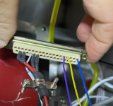 3 pins to navcom purple yellow blue.png3.2 MB · Views: 226
 -
 Packing Slip.png12.9 MB · Views: 276
 -
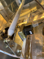 Pitch servo in empenage.png14.8 MB · Views: 281
 -
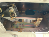 Roll servo in right wing.png13.1 MB · Views: 267
 -
 Wires in progress.png15.8 MB · Views: 238
 -
 Disassembly.png10 MB · Views: 195
 -
 Wiring Harness.png11 MB · Views: 244


")
