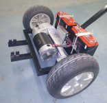
Recently did a re-power of an older
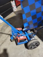
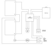
Dragger brand nosewheel tug. The original had a solid axle (i.e. no differential), so it's hard to turn, plus it's single speed...jerky start when loaded and very slow when empty. It could not be dragged around the hangar comfortably when power off. The transaxle has a differential...no problem for a hard surface, but it may spin one side on grass or ice. Flip side, it's easy to steer, and I use a contactor in the motor lead so it doesn't try to be a generator when you drag it around.
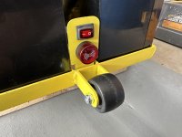
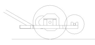
The nosewheel capture is interesting. There is no attempt to lift the tire, although you can bear down on the handle to increase traction. The tire simply rides between side and fore/aft rollers.
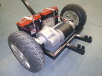
I installed a somewhat larger motor (800W) than the one used on the simple tug design published by Reinhardt Metz here and in Kitplanes. An experiment really, as I wanted to explore what was necessary to move some of the heavier airplanes (Bonanza, Seneca, etc) based here at 08A.
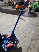
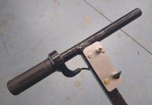
What I learned is that the cheap speed controllers on Amazon don't seem to handle the initial amperage inrush of the big motor when starting a heavy airplane from rest (the test subject was an A36, slightly uphill in an out of a hangar). It's possible I simply got a badly assembled controller, but I think they're just lying about short term 100 amp capacity. And I could be entirely wrong in my opinion. There is some good discussion in
this thread.
Anyway, I sidestepped the issue by installing a
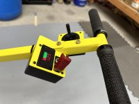
Dimension Engineering SyRen 50. Good quality, programmable, with regen, and built in 100 amp overcurrent protection. The only downside is it won't accept input from a common Hall effect throttle, like the scooter thumb throttle in the photo below. It requires a resistive pot, and the only suitable one I could locate was a
Magura 317 twist grip. Works great however; smooth from zero speed to a fast trot.
If you don't mind the additional expense of the SyRen controller and Magura twist grip, it's a good upgrade. Note I use a different Dimension controller for the dual motor tug, and I've zero failure reports.
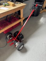
The dual motor tug remains my personal favorite. I may yet try to integrate a dual system into a nosewheel tug.


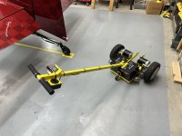
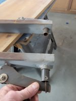


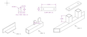
 I also wondered if a simple U bolt could be used to mount the transaxle to the frame versus the vertical weldments you have on the drawings?


