
Van's Air Force
You are using an out of date browser. It may not display this or other websites correctly.
You should upgrade or use an alternative browser.
You should upgrade or use an alternative browser.
Wiring panel on bench
- Thread starter ERJDriver
- Start date

cvairwerks
Well Known Member
Don't forget service loops....
PilotjohnS
Well Known Member
Make tooling
*Make some tooling to hold the harness service loops to get very consistent wire loops and stuff. It seems to really help to have very pretty harness runs when it comes time to install in plane.
*Keep things done low so they can be serviced once inside.
*Think about connector access, and removal of connectors once in the plane remembering there is only real access from the bottom.
*Use good quality connectors, crimpers, etc. It is a real pain to redo crimps and stuff once everything is in the plane.
Carl Froehlich
Well Known Member
I recommend you divide the panel into two parts:
- What says in the airplane
- What comes out with the panel
On the RV-8 and RV-10 the stock Van’s panels make this easy. The RV-8 has side wings to mount breakers and switches. The RV-10 has a lower apron for these. This stuff, along with remote XPDRs, ARINCS, Radio, EMS modules and such are things that stay in the airplane. Once the removable part of the panel is out, all these have easy access.
For the RV-6 and 7 you can modify the panel to cut the bottom off and add this lower apron. The RV-14 requires more creativity.
The majority of panel wiring is then the interconnected stuff between the TSO GPS navigator and audio panel, along with wiring to D connectors to the rest of the plane. The EFIS displays are all on a D connector, so wiring to the rest of the stuff says in the plane when you disconnect the EFIS.
Modern network EFIS systems makes this division easy.
As far as the removable part of the panel connections, I use two 25 pin D connectors for everything other than power. For power I mount four breakers on the panel (for me two breakers for the GTN-650, one for the audio panel and one spare). Power to these breakers is via a single molex plug (or whatever plug you like that can handle the current). These connectors are easy to access once the panel screws are out and the panel comes toward you a few inches.
Do this and you will never again be on your back with your head under the panel.
Carl

Mike Buckler
Member
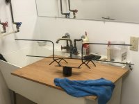
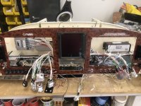
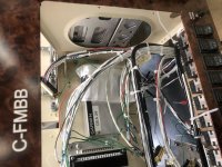
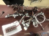
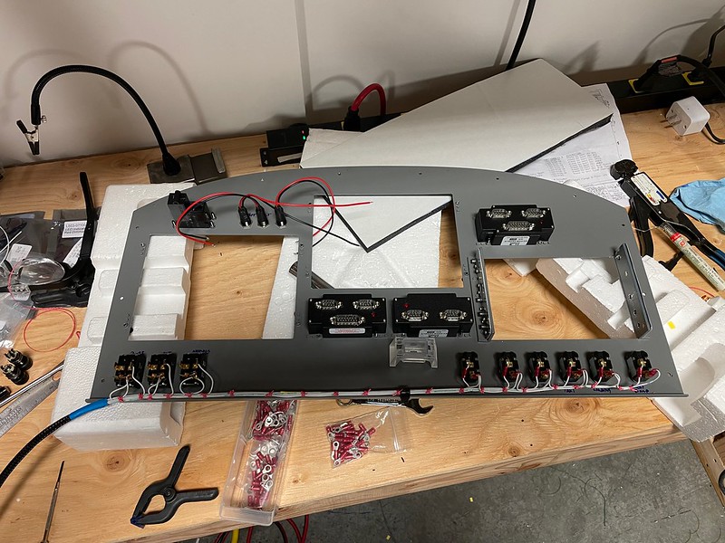
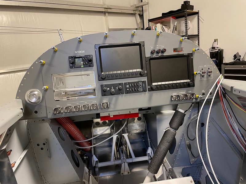
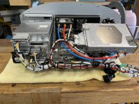
Building an RV 14 panel. I welded up the frame in the 1st picture. Then placed the frame in behind the panel, to keep the wire run neat and grouped together. You can see this in the 2nd and 3rd pictures. I used zip ties to temporally hold the wires in place. The 4tH picture shows removing the zip ties and hand lacing the harness. I hope this is helpful for you as it worked well for me.
Attachments
N804RV
Well Known Member
Are people using D-subs, CPC or Deutsch connectors within their harness to allow for things to be removed?
Most of the Deutsch style connectors I've seen have large pins for 16/18G wire. And, the biggest ones I've seen are 12 positions.
I'm using a 25 pin standard density Dsub connector for the switch wiring on my RV8 center instrument panel. The male connector will be hard mounted on a bracket riveted to the avionics shelf. The GNS430 and PMA6000 trays stay mounted to the avionics shelf and the complete center panel is removeable.
Last edited:
My best tip: Don't Do It... ")
I confess that I did not setup or test my avionics on the bench with my most recent build, but rather wired everything directly in the airframe. I've found it's a major hassle to build a harness, and then pull those completed harnesses through the panel, potentially with extra connections. I've never able to get my harnesses as accurate in length as when I pull and terminate in the airframe - leading to a more efficient install.
I understand the desire to connect and bench check everything, but IMHO, if you're doing your own avionics - building your harness in place results in a better product.
I use all D-Sub in the panel staying consistent with Garmin, WeatherProof DC firewall-forward, but use CPC connectors everywhere else except for trim servos, flap positioner and LED lights and any other small wire (22GA and up) connections; for those, I just use d-sub standard pins and sockets directly with heat shrink.
I confess that I did not setup or test my avionics on the bench with my most recent build, but rather wired everything directly in the airframe. I've found it's a major hassle to build a harness, and then pull those completed harnesses through the panel, potentially with extra connections. I've never able to get my harnesses as accurate in length as when I pull and terminate in the airframe - leading to a more efficient install.
I understand the desire to connect and bench check everything, but IMHO, if you're doing your own avionics - building your harness in place results in a better product.
Are people using D-subs, CPC or Deutsch connectors within their harness to allow for things to be removed?
I use all D-Sub in the panel staying consistent with Garmin, WeatherProof DC firewall-forward, but use CPC connectors everywhere else except for trim servos, flap positioner and LED lights and any other small wire (22GA and up) connections; for those, I just use d-sub standard pins and sockets directly with heat shrink.
Last edited:
My best tip, do it
Think access and later needs. Since your area of interest is an 8, the possibilities are plentiful.
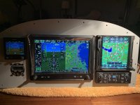
My entire avionics suite is on the center panel is removable and can be worked on at a later time on the bench.
I used CPC connectors. One for power, one for signal.
To remove the center panel, disconnect the pitot/static/AOA, 2 CPC’s, 2 GEA24 connectors (engine and sensor probes), and antennas. 10 minutes later, a fully functional panel goes on the bench and I hook up a CPC plug for power and another for can bus termination.
It also allowed me hours of fun in the demo mode and I was able to do a lot of configuration work. And I was able to test it thoroughly and found a wire had slipped in a solder sleeve on the G5.
I did add additional bracing to the side panels due to weight on the center panel.
Think access and later needs. Since your area of interest is an 8, the possibilities are plentiful.
My entire avionics suite is on the center panel is removable and can be worked on at a later time on the bench.
I used CPC connectors. One for power, one for signal.
To remove the center panel, disconnect the pitot/static/AOA, 2 CPC’s, 2 GEA24 connectors (engine and sensor probes), and antennas. 10 minutes later, a fully functional panel goes on the bench and I hook up a CPC plug for power and another for can bus termination.
It also allowed me hours of fun in the demo mode and I was able to do a lot of configuration work. And I was able to test it thoroughly and found a wire had slipped in a solder sleeve on the G5.
I did add additional bracing to the side panels due to weight on the center panel.
Attachments
Last edited:
Anyone have any tips as far as wiring a panel on the bench?
To figure out how to route the wires, where to split off for components and to figure surface loops lengths, I used a colored cord as the main wiring cable path. Then I used parachute cord to simulate individual cables going to a component. The parachute cord was just taped to the main cord and each parachute cord was labeled with the component name on tape.
Here's a video of the the process of figuring that out.
EDIT: When done the cords were carefully extracted from the fuselage and then measured. A diagram with all the lengths was made from the measurements.
Last edited:

