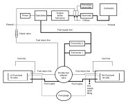
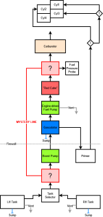
I've been troubleshooting a few fuel issues/questions and I realized I don't really understand the fuel system as a whole. Tracing the lines left me more confused.
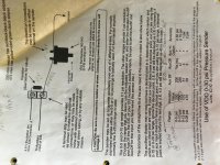
I consulted the RV-6A build manual I received when purchasing this aircraft (I'm the 4th owner), but I only see an extremely brief description of fuel hoses, boost pump, primer, etc. and a diagram of "typical fuel / oil hose routing". These resources don't actually describe the system as a whole, such as which component comes after which component in the path.
Anyway, here's the behavior that's puzzling me:
- With the engine OFF...
Flow: If I turn on the boost pump the fuel flow reads 2.0 GPH. Obviously there is no fuel flowing into the carburetor, so this seems to be just 2.0 GPH of fuel flowing around in a circle. This is what initially caused me to start tracing lines, wondering where the fuel was flowing to.
Pressure: However, what really concerns me here is that the fuel *pressure* remains at near zero (0.1-0.3 psi) when the boost pump is on. If the mystery line is some sort of relief valve, I'd still expect full boost pressure.
- When the engine is ON...
Flow: I see 4-5 GPH as expected (that is normal for taxi, right?). But if the pump is capable of circulating fuel here, then I'd expect to always always see a +2 GPH increase with the boost pump on, but I've never noticed that.
Pressure: Typically 2-3 psi, but that would be due to the engine-driven pump taking over the role.
- In flight, I see behavior that might be considered odd.
Flow: Occasionally in cruise, with no other factors changing (no leaning adjustments, no temperature changes), the GPH will gradually shift +/- 0.5 GPH.
Pressure: Fuel pressure is also constantly changing, with no apparent pattern, anywhere from 2.0 to 5.5 psi. Turning the boost pump on _seems to_ provide a pressure boost, maybe, hard to tell as it's not a definitive "boost" as I'd expect.
Could anyone help me answer a few questions...
1. What is the "mystery line" and the devices on each end for?
2. With this fuel system design, and based on the behaviors I described, is the boost pump actually providing any protection in case of engine pump failure?
3. What increase in pressure "should" I be seeing when the boost pump is on?
4. How do you all typically test this stuff?
5. Is there any official recommendations of fuel system design I just haven't found yet?
6. Is it just me, or is 2.0 GPH really really low for a boost pump. Shouldn't it be at least 8.0 GPH, to provide full cruise power for the engine?
Attachments
Last edited:
")