Van's Air Force

The definitive Van's Aircraft support community! Buying, building or flying an RV? Join our exclusive family of mentors and enthusiasts!

What fittings to use for plumbing manifold pressure to (2) Surefly SIMs and GRT EIS

MauleDriver

Well Known Member
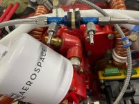
I am in the process of replacing both mags with Surefly SIMs (electronic ignition units). Having trouble specifying what fittings I can use to tap into my current MP with 2 lines that will go to the SIMs.

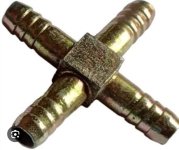
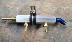
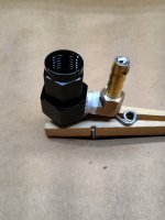
Currently I have a hose going from cylinder 5 through the firewall with a bulkhead fitting to a pressure sensing unit that is part of my GRT EIS. I want to tap into that line and route flexible tubing to both SIMs. The flexible tubing should be used with barbed nipple.

Interested in seeing what kind of fittings others may have used to do something similar.Bulkhead MP fitting.JPEG
 
Why not just install a 1/8 NPT brass fitting in cyl #6 and run dedicated lines to your ignitions....
Use a splice connector before the T fitting and make a restriction in the splice.
 
I did similar to what Gasman suggests.

On my machine the outlet for the EIS MAP sensor remains on a stand-alone fitting in the #3 cylinder. When I installed the second SUREFLY I placed a brass fitting in the #4 cylinder and used a barbed tee up near the left SIM to split the MAP line to each side. Where you place the restrictor is up to you but I would prefer having it at the cylinder so that if the line comes off you don't have a large MAP leak. For my restrictor I used the brazing method to fill the end of the fitting then drilled the tiny hole afterwards. There are other methods of course... roll your own, or you could go out and buy a snubber.

For your engine and where you're at right now, a cheap barbed 4-way brass fitting from the auto shop will be perfectly fine. Stay away from the plastic versions on the firewal forward as they're more likely to be affected by the heat in the long term.
 

Attachments

  • Screenshot_20250407_071551_Google.jpg
    Screenshot_20250407_071551_Google.jpg
    83.9 KB · Views: 1
Last edited:
I run dual pMags. A buddy of mine turn out these manifolds. I use the Van’s MP 1/4” braided hose to connect the AN fitting to the engine manifold pressure fitting. The two small barb fittings go to the pMags. The larger barbed fitting goes to the EMS manifold pressure sender.

PM me if you’re interested in getting a set. He recently made a batch.

Carl
 

Attachments

  • 20250406_173329.jpeg
    20250406_173329.jpeg
    1.4 MB · Views: 99
Your original suggestion of simply tapping #6 cylinder with a brass barb fitting and giving the (2) SIMs their own feed seems on target and I’ll do it unless this fitting is available somewhere…where does one find such a thing? It’s what I dreamed of but didn’t think existed. DIY?

I didn’t know a restrictor was called for but it makes sense. I would think it would smooth out the pressure signal and mitigate any failure in the plumbing.
 
I run dual pMags. A buddy of mine turn out these manifolds. I use the Van’s MP 1/4” braided hose to connect the AN fitting to the engine manifold pressure fitting. The two small barb fittings go to the pMags. The larger barbed fitting goes to the EMS manifold pressure sender.

PM me if you’re interested in getting a set. He recently made a batch.

Carl
Nice unit there. If I were doing this from scratch, I’d use it. Thanks!
 
Nice unit there. If I were doing this from scratch, I’d use it. Thanks!
Many ways to do this. Yes, we recommend a restrictor fitting in the cylinder, to dampen the pressure pulses. On the engine side of the firewall, you could use a gauge port fitting, similar to what Warren showed above, connected to a AN825-3D, then get 2, -3 fitting stems to connect to the PMag hoses. The stainless ones we use ar on the tee in this pic.

Tom
 

Attachments

  • DUAL PMag tee 2.jpg
    DUAL PMag tee 2.jpg
    128.6 KB · Views: 92
I did similar to what Gasman suggests.

On my machine the outlet for the EIS MAP sensor remains on a stand-alone fitting in the #3 cylinder. When I installed the second SUREFLY I placed a brass fitting in the #4 cylinder and used a barbed tee up near the left SIM to split the MAP line to each side. Where you place the restrictor is up to you but I would prefer having it at the cylinder so that if the line comes off you don't have a large MAP leak. For my restrictor I used the brazing method to fill the end of the fitting then drilled the tiny hole afterwards. There are other methods of course... roll your own, or you could go out and buy a snubber.

For your engine and where you're at right now, a cheap barbed 4-way brass fitting from the auto shop will be perfectly fine. Stay away from the plastic versions on the firewal forward as they're more likely to be affected by the heat in the long term.
This is what I'm going to do. Have a brass fitting for the cylinder and an aluminum T to split it for the SIMs. I'll add a blob of solder and drill a hole at the brass fitting.

This way I leave the existing MP connection untouched, which is good since it works.

Thanks!
 
This is what I'm going to do. Have a brass fitting for the cylinder and an aluminum T to split it for the SIMs. I'll add a blob of solder and drill a hole at the brass fitting.

This way I leave the existing MP connection untouched, which is good since it works.

Thanks!
Can you post a picture of your solder blob restrictor? Maybe I'll do that with the fitting dbeach found.

Thanks.
 
The only further comment I can make is that the oriface for the MAP snubber needs to be as small as you can make it. I'm talking really small. If you can get it down to 0.020" that would be good. A 1/16" hole is far too big.
 
The only further comment I can make is that the oriface for the MAP snubber needs to be as small as you can make it. I'm talking really small. If you can get it down to 0.020" that would be good. A 1/16" hole is far too big.
Typically we use .040 orifice restrictors. We have done one that was .016. Dont remember why so small, but the client wanted it that way.
 
Back
Top