What's new
Van's Air Force

Don't miss anything! Register now for full access to the definitive RV support community.

VPX Pitch Trim Indication GDU 460 (G3X)

KatanaPilot

Well Known Member
VPX Pitch Trim Indication GDU 460 (G3X) - not 9.21 issue

This is not a G3X S/W 9.21 issue. Airplane is running 9.14.

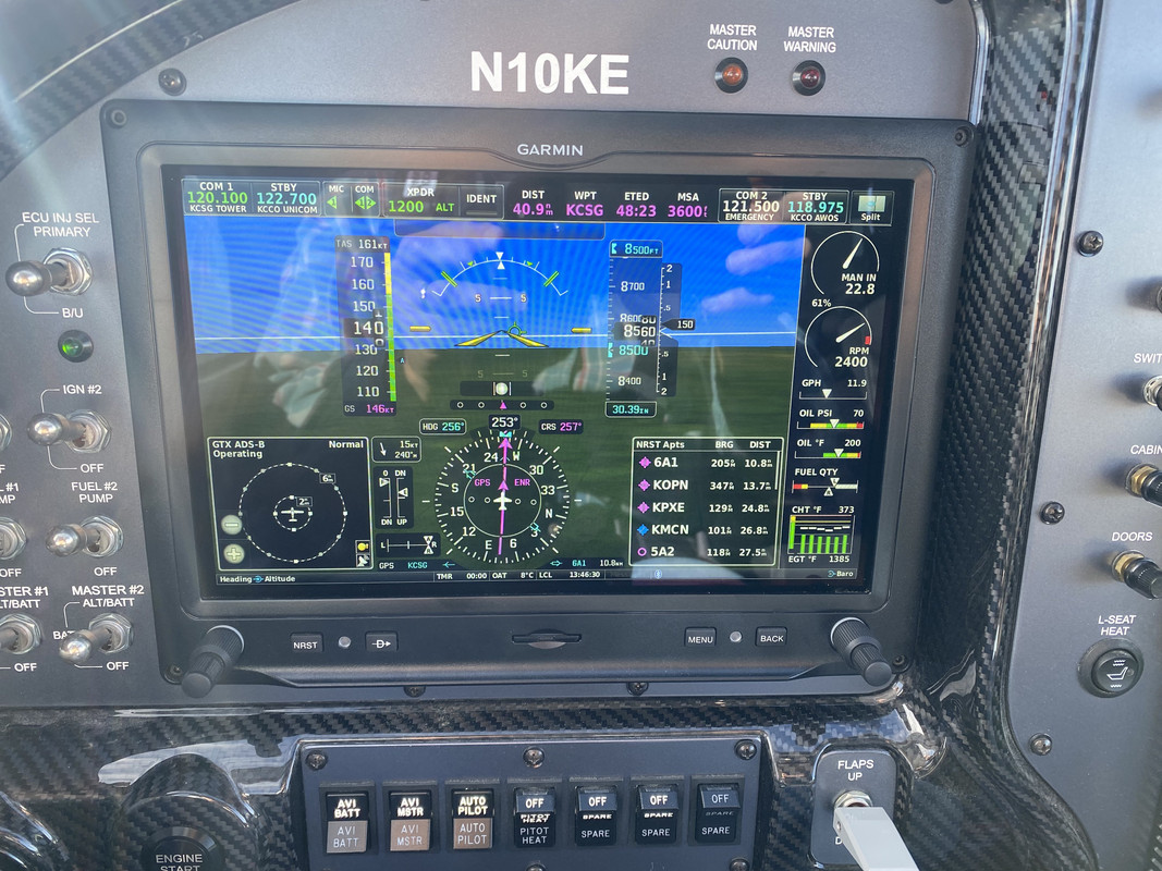
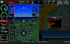
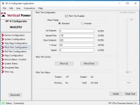
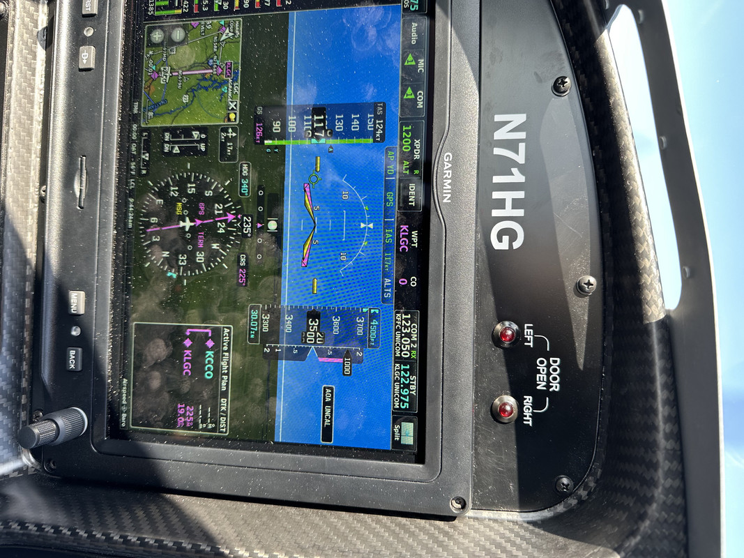
Trying to help out a fellow builder in my Tech Counselor role. Her new RV-10 has an issue with the pitch trim indication - specifically the location of the neutral tick mark on the display. It is way offset from the center of the display range. The pitch trim operates and displays properly, other than the neutral mark.

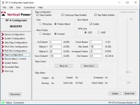
All trims are routed though the VPX. Standard Ray Allen servos.

I looked at my RV-10 (same setup) and my neutral tick mark is very close to center. My RV-7 is slightly offset from center, but not to the extreme of hers.

Chad (Astronics) - if you see this message, I have also sent you a PM via VAF.

Wondering if anyone has had this issue before and found a solution. Thanks.

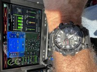
Sorry the image is rotated. Brad, if you are around, feel free to fix it! ;)

 
Last edited:
Tick mark

I'm assuming you checked the VP Configurator where the tick mark is set if I remember my set-up correctly. Mine is set at take-off trim. The RV-14 (also the 10) is very pitch sensitive and helps getting this correct.
 
The VPX has a neutral position trim setting. We set ours so that it centers the display in cruise, and requires about 1/3 nose down trim for takeoff. If you want it centered in the display at takeoff, you should be able to set it to TO trim, note the position reading, and use that as you're "neutral trim" number in the VPX config.
 

Attachments

  • Screenshot_20230427-073713.jpg
    Screenshot_20230427-073713.jpg
    227.8 KB · Views: 75
Thanks for the replies.

So far, it does not appear there is any way to force the neutral tick mark to the center of the display bar. I guess we just got lucky with our RV-10.

The only other thought I had was to rig the trim with the servo in the neutral position - but that's not exactly how the plans show to do it.

 
VP-X Configurator settings

This what my screen and settings look like in VP-X Configurator. You can make a tick mark any position you want. These are my take-off settings for flaps and elevator trim.
 

Attachments

  • g3x2.jpg
    g3x2.jpg
    254.5 KB · Views: 79
  • FLAP.jpg
    FLAP.jpg
    104.1 KB · Views: 90
  • PITCH.jpg
    PITCH.jpg
    86.5 KB · Views: 82
Last edited:
Trim

The issue is how the trim system is mechanically rigged.

I tried numerous iterations but ended up with the neutral trim tick mark offfset from the gauge center. Works fine…
 
Yes, her trim works fine as well. We were trying to force the neutral tick mark towards the center of the bar graph, but it appears that may not be possible.

Not sure why you would want a reference mark for anything but the takeoff position, but that’s just me.
 
exactly

Yes, her trim works fine as well. We were trying to force the neutral tick mark towards the center of the bar graph, but it appears that may not be possible.

Not sure why you would want a reference mark for anything but the takeoff position, but that’s just me.

Yep, the tick mark shows neutral trim. the center of the gauge range only shows the center of the servo movement, which in this case, is not at the same point as neutral trim.
 
Yep, the tick mark shows neutral trim. the center of the gauge range only shows the center of the servo movement, which in this case, is not at the same point as neutral trim.

Which is interesting given that the instruction manual infers that the center mark does not have to be at the center of travel, but the trim neutral mark would be in the center of the display.

I'm sure I'm reading this incorrectly.

 
My neutral tick mark

is near the top of the indicator. To me that makes sense cause there is more nose up travel than nose down travel. It doesn’t make sense to have the neutral point in the middle but that’s my opinion.
 

Attachments

  • IMG_1476.jpg
    IMG_1476.jpg
    510.2 KB · Views: 31
Which is interesting given that the instruction manual infers that the center mark does not have to be at the center of travel, but the trim neutral mark would be in the center of the display.

I'm sure I'm reading this incorrectly.


The range of 0 - 255 represents the total range of motion of the servo, regardless of where the trim tab neutral setting is. So 0 might represent the servo at its full down limit and 255 would represent the servo's full up limit.

If the servo were connected directly to the trim tab, one could center the tab coincident with the center of the servo range of motion. In this case, neutral trim tab position would occur in the center of the gauge range (which represents the travel of the servo). In the -10, it doesn't seem to work out that way. My tick mark for neutral trim is at about 35% of the gauge scale.

It really doesn't matter, though, as what you need to know is where neutral trim tab position is...
 
In my experience I have found that the sensor range 0 to 255 is not very linear, and can vary from servo to servo. I found one install where the last 50 to 80 positions on the sensor happened at the last 1/8" of travel (or less). Sooo, to cheat it, I just bias the number down (or up) for full deflection. Get it more on the linear part of the scale, then things seems to neutral out better and a bunch of the indicated movement doesn't happen at the very end of the actual stroke.

Tom
 
Back
Top