

Hello Group,
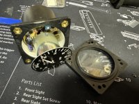
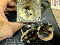
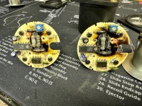
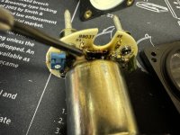
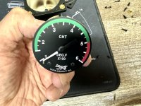
Last week while flying my RV-4, I had a burning smell in the cockpit. Checking the panel, both the EGT and CHT instruments weren’t working and were hot to the touch. After returning to the field, and removing them, I disassembled both and found that both circuit boards (nearly identical boards in each) had burned spots around the resistors in the middle. There was also moisture on the inside of the glass on both. Voltage was in the normal range. Running Earth X battery.
Looking for ideas on what caused this. See photos.
Jim
Attachments
-
 6CAB66F3-8C96-4796-A8D9-AC39E00A8428.jpg386.5 KB · Views: 110
 -
 D9844423-F93D-47AD-8269-D1DBD46887B3.jpg483.3 KB · Views: 85
 -
 F89C6B22-1F2B-4D8D-96B0-278DD4AF3522.jpg647.9 KB · Views: 125
 -
 CD036B27-0989-4188-AFB1-39BC400D1F24.jpg367.5 KB · Views: 97
 -
 6E2BB9BD-375E-4F4B-8AD7-2AA6C82E716C.jpg324.9 KB · Views: 85

