Peter
I attach some photos and made some measurements which may be of help. Sufficient Drill Clearance can be achieved to drill and remove the AN470-4's along the top flange of the weldment with the following:
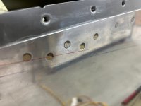
A fore-aft cut beginning between Rivets 5 & 6 on the Firewall (this is about 4 3/4") up from the corner of the Upper Fwd Fuse Assembly skin).
A lateral cut going up between the top row of AN426-3 Rivets 6 & 7 (counting from the firewall) on the side channel, (this is about 5 3/4").
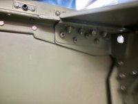
The General View shows the structure without the Upper Forward Fuselage Assy in place. The black line is as far as the Weldment goes along the C-Channel. The Right Upper Weldment shows how it sits against the side skin, its not a right angle which requires the use of the angle-drill. Sufficient Drill clearance can be achieved with the fore-aft cut from the firewall in line with Rivet 5 on the firewall, but you probably need to go between Rivets 5 & 6 for the joint not to be at a rivet.
I marked the Upper Forward Fuselage Assembly with the above lines, (the inside edge of the green tape). The depth of the cut-out looks a lot but the skin tends curves more tightly when in place. The red mark shows where 4 3/4" comes to at the aft end, the whole thing tapers but it gives you the idea. You may get away with lees of a cut-out using the angle drill to remove the rivets but may have difficulty getting an 1/8 punch in to remove the rivet head.
Hope this makes sense!
Leo
View attachment 74147View attachment 74148View attachment 74146View attachment 74145View attachment 74149
RV-10 #40699
END