

JurgenRoeland
Well Known Member
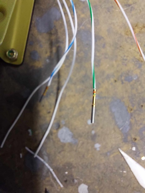
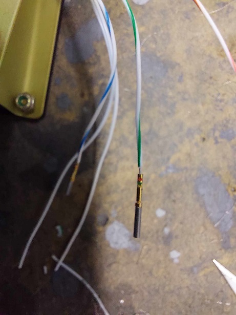
Hi all, I'm in the process of wiring the elevator pitch trim servo. It's the standard ray allen motor. I read in the vpx manual and saw an illustration video how people crimp dsub pins on the wires that come out of the motor and then connect the dsub pins one by one. Then putting heatshrink over each pin to secure the connection.
I tried multiple times and the crimped pins keep moving or coming of of the stripped wire after crimping. I guess the AWG size is just too small. After trying normal dsubs, I switched to high density pins and using the steinair High Density Positioner for SAT-004 crimp tool.
an illustration can be seen in the images.
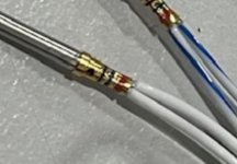
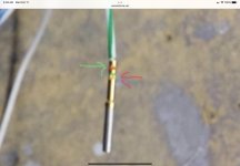
I tried again by winding up the wires (thinking this would increase the gauge a bit) but even then, with high density pins, I can pull the pin of by applying little force on a pull test.
I'm using the high quality stripper SAT-005 of steinair on the 26 awg size wire and can not see any strands cut off.
scratching my hear on what I'm doing wrong and getting worried I won't have any wire left on the motor.
Anybody any suggestion or any other good method to connect the wires to the connecting cable ?
I tried multiple times and the crimped pins keep moving or coming of of the stripped wire after crimping. I guess the AWG size is just too small. After trying normal dsubs, I switched to high density pins and using the steinair High Density Positioner for SAT-004 crimp tool.
an illustration can be seen in the images.
I tried again by winding up the wires (thinking this would increase the gauge a bit) but even then, with high density pins, I can pull the pin of by applying little force on a pull test.
I'm using the high quality stripper SAT-005 of steinair on the 26 awg size wire and can not see any strands cut off.
scratching my hear on what I'm doing wrong and getting worried I won't have any wire left on the motor.
Anybody any suggestion or any other good method to connect the wires to the connecting cable ?
")

