Van's Air Force

The definitive Van's Aircraft support community! Buying, building or flying an RV? Join our exclusive family of mentors and enthusiasts!

The Most Elaborate Cowl Flap Systems = Show Us Let's Discuss.

jackking123

Well Known Member
Patron
I started a thread "Servos for Carb Heat and or Alternate Air". The question was using servos or linear actuators to move the carb heat door in a Van's FAB. I am unlikely to do that, will likely use a Teleflex push pull control cable, but in the process talented and creative builders have come up with some articulating cowl flaps. Very impressive. I thought it would be cool to see (pun intended), what others have done, if they would do it again and what was the effect of deviating from the standard design. How much weight? Cost? Would you do it again?

SHOW US YOUR FANCY COWL FLAPS, FROM SIMPLE TO WILD, MANUAL OR ELECTRO MECHANICAL ACTUATION.
If you have a thread already on your special cowl flaps, please link to that.
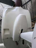
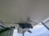
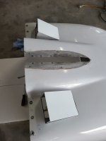
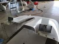
Hope I am not violating rules but here are the pictures from above thread: (nice job Gents)
DanH

https://www.vansairforce.net/attachments/rac-servo-600p-jpg.76396/
hgerhardt
https://www.vansairforce.net/attachments/1734299748933-jpeg.76362/
https://www.vansairforce.net/attachments/1734299951893-jpeg.76363/
 
Last edited:
Jack, lot of stuff in this old thread. Post 144 is a drawing of a key design point, the arrangement of levers so (1) there is very little static load on the plastic servo gears when the door is closed, and (2) required effort to close is reduced as air load increases. The second point would be useful even if you operate with a push pull cable.

 
Jack, lot of stuff in this old thread. Post 144 is a drawing of a key design point, the arrangement of levers so (1) there is very little static load on the plastic servo gears when the door is closed, and (2) required effort to close is reduced as air load increases. The second point would be useful even if you operate with a push pull cable.

Thanks Dan, yes that was the thread.... good stuff. Happy New Year.
 
I started a thread "Servos for Carb Heat and or Alternate Air". The question was using servos or linear actuators to move the carb heat door in a Van's FAB. I am unlikely to do that, will likely use a Teleflex push pull control cable, but in the process talented and creative builders have come up with some articulating cowl flaps. Very impressive. I thought it would be cool to see (pun intended), what others have done, if they would do it again and what was the effect of deviating from the standard design. How much weight? Cost? Would you do it again?


And like I discussed in the other thread I applied the “…what problem are you trying to solve…” approach. While I fully agree that RV’s cool “fine”, the fact remains that their wide speed range means they overcool at high speed and under cool at climb. That’s why a cowl flap is a recurring theme. I initially went down that route and toyed with a variety of variable geometry exits before I landed on a solution that did what I want without any mechanical manipulation. At its core, you want more airflow at slow speeds and less airflow at high speeds, and that problem is elegantly addressed with augmentor tubes.

I also tried some versions of the concept, but the lightest, easiest and least expensive version has proven to be the one that works best.
IMG_20221001_090154266.jpg

The entire cowl outflow goes through those two tubes (5 inch at the bell mouth, 4.5 inches at the outlet), and my inlets are smaller than the stock RV -8 in area. This is good enough to cool a high output 540 in a VX climb out of Mojave after a fuel stop in the middle of Summer and also typically shows good CHT and a tight (< 20 degree) spread across all 6.

All this with no linkage, knobs, actuators or pilot action of any kind. Just a thought to throw out there.
 
Last edited:
I know absolutely nothing about them but I didn't want additional weight or another control in the cockpit. I opted for a ground adjustable cowl louvers.
They are the standard Vans louvers. I added a fiberglass gate to each. They are slotted for the screws. The louvers inside have nutplates. Adjustment is simple. Loosen the eight screws. Take a pick and slide the gate to the desired position. Tighten the screws. No idea if they will work. She hasn't flown yet.
Left side is almost closed. Right is almost fully open.

20221028_111943.jpg
 
And like I discussed in the other thread I applied the “…what problem are you trying to solve…” approach. While I fully agree that RV’s cool “fine”, the fact remains that their wide speed range means they overcool at high speed and under cool at climb. That’s why a cowl flap is a recurring theme. I initially went down that route and toyed with a variety of variable geometry exits before I landed on a solution that did what I want without any mechanical manipulation. At its core, you want more airflow at slow speeds and less airflow at high speeds, and that problem is elegantly addressed with augmentor tubes.

I also tried some versions of the concept, but the lightest, easiest and least expensive version has proven to be the one that works best.

The entire cowl outflow goes through those two tubes (5 inch at the bell mouth, 4.5 inches at the outlet), and my inlets are smaller than the stock RV -8 in area. This is good enough to cool a high output 540 in a VX climb out of Mojave after a fuel stop in the middle of Summer and also typically shows good CHT and a tight (< 20 degree) spread across all 6.

All this with no linkage, knobs, actuators or pilot action of any kind. Just a thought to throw out there.


Augmenter Tubes.... Ohhhhhhhh, Ahhhhhhh. Ha ha. I love those. I owned a 1958 Piper Apache Twin PA23-160 in the early 90's. Flew it for 3 years.
It had augmenter tubes. People use to comment on how it sounded when I flew over the airport.

Admit I don't know if I understand how they work. I get the low pressure creating more airflow through cowl for cooling at low speed. At high speed I assume the sizing was made so it's optimal at high speed as well, while still getting some augmenter benefit.

AI to the rescue, explaining the Piper Apache Augmenter set up.

"A Piper Apache's augmenter tube exhaust system works by directing the engine exhaust gases through tubes located on the outboard side of each engine, essentially creating a low-pressure area that draws additional cooling air through the engine compartment, enhancing engine cooling while also providing a small amount of additional thrust by utilizing the exhaust gases' energy; this system eliminates the need for cowl flaps or cooling flanges on the cowling, allowing for higher speeds due to reduced cooling drag.

Key points about the augmenter tube system:
  • Exhaust gas redirection:
    Exhaust gases from the engine are channeled into the augmenter tubes on the outside of the engine.

  • Low-pressure area creation:
    As the exhaust gases flow through the tubes, they create a low-pressure area which draws in additional air from the engine compartment.

  • Cooling benefit:
    This air intake helps to cool the engine effectively, eliminating the need for traditional cooling mechanisms like cowl flaps.

  • Slight thrust augmentation:
    The exhaust gases also contribute a small amount of additional thrust by further accelerating the air drawn into the system. "
 
Last edited:
I know absolutely nothing about them but I didn't want additional weight or another control in the cockpit. I opted for a ground adjustable cowl louvers.
They are the standard Vans louvers. I added a fiberglass gate to each. They are slotted for the screws. The louvers inside have nutplates. Adjustment is simple. Loosen the eight screws. Take a pick and slide the gate to the desired position. Tighten the screws. No idea if they will work. She hasn't flown yet.
Left side is almost closed. Right is almost fully open.
Nice idea... I am going stock on my RV-7 and we shall she. Not painting right away so I will be able to experiment and mod as needed.

So question how does it work? Cooling good on hottest day climb, and temps not too low in cruise on coldest days?
 
Nice idea... I am going stock on my RV-7 and we shall she. Not painting right away so I will be able to experiment and mod as needed.

So question how does it work? Cooling good on hottest day climb, and temps not too low in cruise on coldest days?
I have a stone stock -7 cowl. I am going with the anti-splat electric cowl flap to gain easy access the gascoalator drain and provide cooling. As my aircraft was built you’d have to remove the lower cowl to drain the gascoalator.

 
My set up. I really like the ability to cool down the engine on the hottest of days.
 

Attachments

  • 1000001569.jpeg
    1000001569.jpeg
    3.2 MB · Views: 165
  • 1000001568.jpeg
    1000001568.jpeg
    2.5 MB · Views: 161
  • 1000001566.jpeg
    1000001566.jpeg
    2.9 MB · Views: 160
Nice idea... I am going stock on my RV-7 and we shall she. Not painting right away so I will be able to experiment and mod as needed.

So question how does it work? Cooling good on hottest day climb, and temps not too low in cruise on coldest days?
We shall see. She hasn't flown yet
 
And like I discussed in the other thread I applied the “…what problem are you trying to solve…” approach. While I fully agree that RV’s cool “fine”, the fact remains that their wide speed range means they overcool at high speed and under cool at climb. That’s why a cowl flap is a recurring theme. I initially went down that route and toyed with a variety of variable geometry exits before I landed on a solution that did what I want without any mechanical manipulation. At its core, you want more airflow at slow speeds and less airflow at high speeds, and that problem is elegantly addressed with augmentor tubes.

I also tried some versions of the concept, but the lightest, easiest and least expensive version has proven to be the one that works best.
View attachment 77109

The entire cowl outflow goes through those two tubes (5 inch at the bell mouth, 4.5 inches at the outlet), and my inlets are smaller than the stock RV -8 in area. This is good enough to cool a high output 540 in a VX climb out of Mojave after a fuel stop in the middle of Summer and also typically shows good CHT and a tight (< 20 degree) spread across all 6.

All this with no linkage, knobs, actuators or pilot action of any kind. Just a thought to throw out there.
Toobuilder - Michael,
Do you have any more details on the augmenter tubes? Length of them? Material? I'm assuming Stainless? How did you make the bell shape or did you purchase that somewhere?
Do you have a space between the augmenter tube and the bottom of the fuse?
How critical is the opening of the exhaust into the augmenter tube?

Thanks for sharing! I like what you did!

Brad
WIP on a RV-10.
The length is 21 inches. No scientific reason - that's just the real estate I had to work with
Material is .016 stainless, rolled in a slip roller and spot welded/riveted
Bell mouth is from one of the automotive turbo supply houses. About $20 each
The front of the tube is attached to the engine mount cross tube with a single Adel clamp and is essentially right up against the original outlet ramp. Rear is on a standoff, secured with a band clamp and the tube is about an inch below the lower skin.
The exhaust pipe end distance was derived using the highly scientific method of blowing a leaf blower into the bellmouth and measuring the speed of the air at the exit. moving the blower nozzle in or out of the bellmouth changed the resulting speed. One inch in front of the lip seemed the best so that's what I went with.

IMG_20210306_140450348.jpgIMG_20210306_155453306.jpg
 
Last edited:
After sealing the upper plenum up tight I was looking for ground cooling with a side of cowl flap.

 
The length is 21 inches. No scientific reason - that's just the real estate I had to work with
Material is .016 stainless, rolled in a slip roller and spot welded/riveted
Bell mouth is from one of the automotive turbo supply houses. About $20 each
The front of the tube is attached to the engine mount cross tube with a single Adel clamp and is essentially right up against the original outlet ramp. Rear is on a standoff, secured with a band clamp and the tube is about an inch below the lower skin.
The exhaust pipe end distance was derived using the highly scientific method of blowing a leaf blower into the bellmouth and measuring the speed of the air at the exit. moving the blower nozzle in or out of the bellmouth changed the resulting speed. One inch in front of the lip seemed the best so that's what I went with.

View attachment 78444View attachment 78445

I really like the simplicity of this approach, but you can't have any mufflers with this setup. In Germany and most european countries we have the problem of very hard noise restictions. We need noise measurements for a full power takeoff for the certification of every single experimental aircraft.
Do this tubes reduce the noise or is it even worse, like blowing in a trumpet.?
Maybe build them like a glass pack muffler? Aluminum shell, thin sheet of mineral wool inside, with some thin perforated stainless inside of that? Probably be a bit heavier and not quite as efficient. But I bet it would reduce cabin noise in addition to external "noise pollution".

1736950305670.png
 
Maybe build them like a glass pack muffler? Aluminum shell, thin sheet of mineral wool inside, with some thin perforated stainless inside of that? Probably be a bit heavier and not quite as efficient. But I bet it would reduce cabin noise in addition to external "noise pollution".

View attachment 78562

I tried that exact approach with my Hiperbipe. The muffler failed in only a few hours. We need to remember that the exhaust is glowing orange for hours at a time. The glass pack type muffler has a bunch of relatively fragile perforated tube that does not take well to long duration heat. In mine, the perf tube warped, melted, and broke away, ultimately blocking part of the exhaust path. Not good. And to top it all off, the sound output was not noticeably different from a straight 4-1 collector. From a cabin noise perspective, the most significant reduction in noise was a simple downturn outlet on the collector. MUCH lighter than the glass pack and more effective.

As for the augmentor tubes on the Rocket - I have no idea if there is a change in sound output. It’s loud now, it was loud before. I have noise cancelling headsets.
I'm not sure if I explained what I was thinking. Did you try a glass pack muffler? Or an augmentor tube fabricated like a glass pack? I was thinking the venturi effect drawing in cooler air would allow the perforated tube to live? But it may be size and weight prohibitive, and the perforations may disrupt the airflow too much to gain the cooling benefit.

I think your approach here is perfect. Effective cooling with no moving parts to fail, minimal weight, and minimal if any added drag. The comment from Ingo Weise
just made me curious if a little modification could also get a little noise reduction.
 
I'm not sure if I explained what I was thinking. Did you try a glass pack muffler?
Yes. A glass pack muffler of the same construction you illustrated. The packing around the perf tube makes a great insulator, so there is zero cooling available. I have a picture of the damage somewhere... will post it if I can find it.
 
I'm not sure if I explained what I was thinking. Did you try a glass pack muffler?
Ok, now I think I get it. You are suggesting an augmentor tube with a perforated inner liner - like a screech liner in an afterburner.

That's interesting. I can imagine that would cut some db. Might try that someday!
 
All Piper Apaches. early Aztecs, Aero Commander and Twin Bonanza used augmenter exhaust. Aztec got rid of augmeneors in mid 60's, Commander somewhat later. Not sure about Bonanza. Augmentors were known for being noisy inside and outside the airplane.
 
Not cowl flaps, but my nine has these huge fixed louver vents. I bought her flying so I don't know the background.
Seems to make sense for cooling to roughly match the outflowing area with the inflowing area. They also are quite neat becuase they are formed 'inwards' you can't see them from the side.

Interesting (and perhaps related) this aircraft was orginally built with a Jabiru 8 cyclinder. Not many around and sounds like it was quickly replaced with an O-360.
 

Attachments

  • PXL_20240816_034104472.jpg
    PXL_20240816_034104472.jpg
    1.2 MB · Views: 81
  • PXL_20240816_034327498.jpg
    PXL_20240816_034327498.jpg
    1.3 MB · Views: 81
Last edited:
Ok, now I think I get it. You are suggesting an augmentor tube with a perforated inner liner - like a screech liner in an afterburner.

That's interesting. I can imagine that would cut some db. Might try that someday!
Yea, that's what I was picturing lol.
 
Not cowl flaps, but my nine has these huge fixed louver vents. I bought her flying so I don't know the background.
Seems to make sense for cooling to roughly match the outflowing area with the inflowing area. They also are quite neat becuase they are formed 'inwards' you can't see them from the side.

Interesting (and perhaps related) this aircraft was orginally built with a Jabiru 8 cyclinder. Not many around and sounds like it was quickly replaced with an O-360.
Noticed the antenna insulator bushing is not in the proper position, it is either sliding down the element or the element is loose and ready to depart the aircraft. The bushing shoulder should be tight to die cast housing. Suggest correcting this while it is still fixable.

Antenna.jpg
 
Good overview of the problem here: https://www.kitplanes.com/cooling-outlet-design/

General rule of thumb I use is 2:1 exit area to inlet area; a big reason for that is you want v1*a1=v2*a2, where 1=inlet and 2=outlet, and often v2 = 1/2*v1 due to the drag in the plenum (a good thing in this case, as it relates to engine cooling). Often airplane cowlings have plenty of inlet area, and little thought put into the exit. Wind tunnel or real life testing is generally required to evaluate the required areas and flow paths for a given engine installation.
 
Noticed the antenna insulator bushing is not in the proper position, it is either sliding down the element or the element is loose and ready to depart the aircraft. The bushing shoulder should be tight to die cast housing. Suggest correcting this while it is still fixable.
Well spotted. Thank you. I'll investigate.
 
Back
Top