Hi all,
I am removing a disaster of an electrical system from my (new to me) RV9. I have found many issues - some of which leave me shaking my dang head, and frankly some are downright deadly.
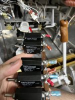
I found this and not sure if I am missing something or if this is another piece of completely wrong wiring.
What's the RED wire to ground that is on the same post as the wire coming from the keyed switch (12v). Ideas?

I am removing a disaster of an electrical system from my (new to me) RV9. I have found many issues - some of which leave me shaking my dang head, and frankly some are downright deadly.
I found this and not sure if I am missing something or if this is another piece of completely wrong wiring.
What's the RED wire to ground that is on the same post as the wire coming from the keyed switch (12v). Ideas?