Van's Air Force
You are using an out of date browser. It may not display this or other websites correctly.
You should upgrade or use an alternative browser.
You should upgrade or use an alternative browser.
Smart glide interconnect/wiring
- Thread starter Mike 1234
- Start date
Dad's RV-10
Well Known Member
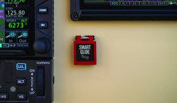
Thanks for the reply. I was looking for the wiring of the switch itself. It’s a backlit switch with five terminals. One goes to a discreet input on the GEA from what I can see in the manual, another to ground. That leaves 3 more for the lighting I think.
To clarify, you're using the Garmin Smart Glide switch?

I´m not familiar with the switch itself, however with five terminals and one light
and a push button switch you will have the following.
Two terminals for the light +12V and GND. If LED light check polarity.
The other three will be the switch, Common/ Normally open and Normally closed. Check with Ohm meter.
Good luck
and a push button switch you will have the following.
Two terminals for the light +12V and GND. If LED light check polarity.
The other three will be the switch, Common/ Normally open and Normally closed. Check with Ohm meter.
Good luck
Thanks Wait, I saw that. The owner requested the switch option.You can also activate from the screen without a switch in case you weren't aware of that.


