
Van's Air Force
You are using an out of date browser. It may not display this or other websites correctly.
You should upgrade or use an alternative browser.
You should upgrade or use an alternative browser.
Shunt location
- Thread starter rwarre
- Start date

If you must have current readings, I suggest ditching the clunky shunt and using a Hall Effect sensor instead. They are available for GRT. This eliminates unnecessary fat wire terminals, fuse-able links and such and their risk of failure.

 www.aircraftspruce.com
I assume the G3X EMS can take this feed, I know Dynon Skyview EMS does.
Carl
Grand Rapids Hall Effect Sensor | Aircraft Spruce ®
Grand Rapids Hall Effect Sensor Grand Rapids hall effect sensor 50amp
I assume the G3X EMS can take this feed, I know Dynon Skyview EMS does.
Carl
Make sure you have a free input that can take this signal. I looked into getting one of these for my Dynon equipped RV-12. The conclusion I came to was that this sensor is an analog voltage output (it irks me that they never really come out and say that, it has to be inferred) and the Dynon SV-EMS-220 only has four inputs that will read an analog voltage. In the case of my RV-12 all four of these "Level C" inputs are already connected to something else. Maybe I missed something or maybe there is another way to skin the cat.If you must have current readings, I suggest ditching the clunky shunt and using a Hall Effect sensor instead. They are available for GRT. This eliminates unnecessary fat wire terminals, fuse-able links and such and their risk of failure.
Grand Rapids Hall Effect Sensor | Aircraft Spruce ®
Grand Rapids Hall Effect Sensor Grand Rapids hall effect sensor 50amp
I assume the G3X EMS can take this feed, I know Dynon Skyview EMS does.
Carl
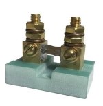
Not sure if you are referencing 2 different style shunts? Putting one on the B-lead is highly recommended so you are looking at probably #8 awg wire. This will give you an indication of an alternator failure in seconds. Normally a battery and alternator are FWF so this kind of device seems more robust than a hall effect donut hanging on a wire FWF. Maybe an A&P or Walt can comment. Adding amp sensing on your primary bus is another good location and since this is behind the panel a hall effect sensor might be more appropriate. And yes, the G3X will detect both locations. I have this type of shunt (pic) FWF on multiple aircraft and never had an issue. Also easy to group with your ANL fuse.Currently doing firewall stuff. I have the g3x shunt and a shunt for the alternator according to the aero electric connection diagram z11. Questions, where is a good location for the g3x shunt and can I read the alt shunt on the g3x. Thanks


Attachments
Last edited:
rapid_ascent
Well Known Member
I didn't see what model you are building anywhere so there may be some differences between models. Mine are mounted below the battery on the firewall adjacent to the main battery and starter contactors. I also made a doubler that I installed on the cabin side for additional support.
The G3X can read 2 current shunts so you should be good to go there.

The G3X can read 2 current shunts so you should be good to go there.
Excellent point. The shunt sense wires need to be fuse protected. They are #26 wires (?) and will turn to smoke if accidentally overloaded. I found some 1 amp fuses that look like little resistors that I wired into the ring terminal. Amazon.If you put in a shunt (not a fan myself, whatever)... I like fuses on the sense wires. Both those wires are otherwise unprotected and have a load of amps available from the alternator and the battery.
