
Van's Air Force
You are using an out of date browser. It may not display this or other websites correctly.
You should upgrade or use an alternative browser.
You should upgrade or use an alternative browser.
Service loop for wing/fuselage connectors?
- Thread starter esco
- Start date

This connection is not the kind you will be working on very frequently (hopefully never!), so I dont think you want much of a service loop. Maybe just some slack in case you need to repin the connector someday.
Enough wire to cut/strip/repin twice is a common theme. And enough additional wire to get out to where you have access with tools to do those things.
This is why we opted for a connector. I wanted to maximize my use of my heated and air conditioned garage at my house. When we got to the hangar I really wanted everything to be plug and play. If this was not a requirement, I'd have done home runs with a small service loop and no connectors or splices.Walt, George, Mark: thanks!
I can use these best practices now in the garage, before I move to a hangar for final assembly.
Gotta love VAF!
Every connector is another potential failure point. While that may not be a big deal for something like a landing light, I didn't want to be cutting up my canbus harness, VOR antenna or pitot plumbing. Since I was going to be pulling that stuff after the wings were on anyway I did the same for all the rest of my wing wiring. I don't have any wing root connectors at all.
When I got to the hangar and installed the wings it only took a few hours to unroll the wiring that was coiled up in the fuselage and pull it through the wing conduit. I left enough service loop under the seat pans that if I ever have to take the wings off in a hay field I can cut the wiring at the wing root and then add a connector when I put it all back together.
If you already have a wiring harness in the wings then yeah, leave enough service loop that you get a couple of do overs.
One additional thought; Sometimes it seems like people get fixated on having the service loop right at the connector. Sometimes it's more convenient or a more secure installation to have the service loop well upstream or downstream of where you think you might need it as long as you can "un-loop" and get enough slack where you want it.
Rather than put more wire in a small wing root."...Sometimes it's more convenient or a more secure installation to have the service loop well upstream or downstream of where you think you might need it as long as you can "un-loop" and get enough slack where you want it."
Nice!
I used butt splices but Desert Rat is right with the exception that every connector has three failure points not just one. Both crimps and the connection itself. I’ve seen failures at each point.
I would have followed Rats ideas but at the time I was doing this, some 20 plus years ago, guys thought they had to have large multi conductor mil spec connectors. I started down that path then got wise and did the butt splices. It was too late to run continuous which is the best idea in my opinion.
My service loops are under the seat pan.
Every connector is another potential failure point. While that may not be a big deal for something like a landing light, I didn't want to be cutting up my canbus harness, VOR antenna or pitot plumbing. Since I was going to be pulling that stuff after the wings were on anyway I did the same for all the rest of my wing wiring. I don't have any wing root connectors at all.
I should add that while I did a wing root connector for all the device wiring, I didn't use one for the VOR antenna. That was a home run that I completed after the wings were mounted. This was not due to a concern for the connector failing, but to try and retain the maximum signal strength from the antenna.
I will say this: the idea that connectors are more prone to failure than a solid wire is objectively true. But I also feel that builders over state this risk which is in fact immaterial. Consider the likely dozens of connectors in your avionics suite today, one more is just not a significant increase in risk. And a quality connector that is well installed, supported properly, and literally never disconnected has a chance of failure that rounds to zero.
I suggest you make the “connector or no connector” decision based on your plans to paint. For example:
- Paint before flying. No connector. Have a little extra wire inside the fuselage in the rare event you have to take a wing off.
- You will paint after flying and you need to take the wings off to paint. Connector.
- You will paint after flying and the wings stay on during paint. No connector.
Carl
- Paint before flying. No connector. Have a little extra wire inside the fuselage in the rare event you have to take a wing off.
- You will paint after flying and you need to take the wings off to paint. Connector.
- You will paint after flying and the wings stay on during paint. No connector.
Carl
Unless you're using waterproof bulkhead mounted cannon plugs, it does seem to me that most of the typical connectors we see in RV style airplanes are probably more prone to failure in a wing root than if they're in a less hostile environment like tucked up under the panel or whatever. Maybe not today, but what about after 30 years of use when my not-yet-existing grandkids are flying and I get the call "papaw, the nav lights quit working."I should add that while I did a wing root connector for all the device wiring, I didn't use one for the VOR antenna. That was a home run that I completed after the wings were mounted. This was not due to a concern for the connector failing, but to try and retain the maximum signal strength from the antenna.
I will say this: the idea that connectors are more prone to failure than a solid wire is objectively true. But I also feel that builders over state this risk which is in fact immaterial. Consider the likely dozens of connectors in your avionics suite today, one more is just not a significant increase in risk. And a quality connector that is well installed, supported properly, and literally never disconnected has a chance of failure that rounds to zero.
")
Please don't think I'm against wing root connectors as a concept. I just think that they shouldn't be the default unless there's a valid reason for them. I chose to sweat it out in the hangar because I didn't want them. Lot's of other guys have been willing to accept the potential (very small) downside because their reason was that they wanted everything to be plug and play when they get to the hangar. Each approach has pros and cons.
The standard Stein fuse harness for the 14 already has a nice service loop at the wing root.
This is why we opted for a connector. I wanted to maximize my use of my heated and air conditioned garage at my house. When we got to the hangar I really wanted everything to be plug and play. If this was not a requirement, I'd have done home runs with a small service loop and no connectors or splices.
I have the same goal- want to keep the project at home as long as possible and a quick final assembly at a future hangar some day.
For those that are experienced with this, what is the consensus/standard practice here?
- Wing has the longer wire for the connection to be made in the fuselage? (I assume this would be the cleaner/dryer environment?)
- Do you cut another fuselage hole for the wire bundle or share the hole with the aileron push tubes?
- High draw items like pitot heat, do you split the + to two different pins? (I see sources with varying claims anywhere from 5A-11A per pin capacity for 0.093" MOLEX)
- And if the 0.093" MOLEX is a sub-optimal choice, is there another connector choice that is more commonly used for wing/fuselage electrical?
Comments welcome
Our excess wire is in the fuselage.
We used the stock exit hole for the wiring harness, but supported it with an Adel clamp at that point
We did a butt splice for the high draw pitot heat wires, because they are out of spec for DSub connectors
DSub for us, but I really like Deutsche connectors from what I've seen.


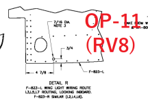
For the 7 you drill a hole about couple of inches from the edge of the aileron push tube hole at about the 5 o'clock position. It's on one of the prints. I imagine the 8 is similar. Fair warning; if you do it that way by the time you get it stuffed full of wire it's too small for most connectors to fit through so in that case your connector would have to be in the wing root area. or go with individual ring terminals or something like that so you can feed wire through into the fuselage one at a time.I have the same goal- want to keep the project at home as long as possible and a quick final assembly at a future hangar some day.
For those that are experienced with this, what is the consensus/standard practice here?
- Wing has the longer wire for the connection to be made in the fuselage? (I assume this would be the cleaner/dryer environment?)
- Do you cut another fuselage hole for the wire bundle or share the hole with the aileron push tubes?
- High draw items like pitot heat, do you split the + to two different pins? (I see sources with varying claims anywhere from 5A-11A per pin capacity for 0.093" MOLEX)
- And if the 0.093" MOLEX is a sub-optimal choice, is there another connector choice that is more commonly used for wing/fuselage electrical?
Comments welcome
Thanks! After I posted I did find a reference OP-11(this is for the '8 which I imagine is similar to '7), which I think is the one you are referring to? Could not find a plan reference for the pitot line into fuselage though... Also I see on some online build log pictures alternative locations were also used... Sometimes I don't know what I don't know... If anyone is cringing, feel free to speak up - always better to know before I drill the holesFor the 7 you drill a hole about couple of inches from the edge of the aileron push tube hole at about the 5 o'clock position. It's on one of the prints. I imagine the 8 is similar. Fair warning; if you do it that way by the time you get it stuffed full of wire it's too small for most connectors to fit through so in that case your connector would have to be in the wing root area. or go with individual ring terminals or something like that so you can feed wire through into the fuselage one at a time.

It did later occur to me that I can have a larger connector on either side of the fuselage wall, I just would have to de-pin/re-pin. After seeing @georgemohr 's bracket, I like that idea and will try do something similar...
Attachments
Last edited:
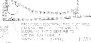
oops, I was remembering this wrong. I just looked and print 28 for the 7 has you enlarge a tooling hole to feed pitot & aoa lines through. I called tech support and they didn't see why I couldn't add a second hole as I described above(which is basically where you show it on the RV8 print) so that's what I did for everything else. As always, it's probably best to pick up the phone and ask for yourself because as you say, it's a lot easier than un-drilling a hole.Thanks! After I posted I did find a reference OP-11(this is for the '8 which I imagine is similar to '7), which I think is the one you are referring to? Could not find a plan reference for the pitot line into fuselage though... Also I see on some online build log pictures alternative locations were also used... Sometimes I don't know what I don't know... If anyone is cringing, let me know- always better before to know before I drill the holes
It did later occur to me that I can have a larger connector on either side of the fuselage wall, I just would have to de-pin/re-pin. After seeing @georgemohr 's bracket, I like that idea and will try do something similar...
Prior to the 10 and 14 I don't think they envisioned the sheer volume of wiring and plumbing that modern avionics would require. I ran into something similar with running the main bundle under the floor and up the aft face of the firewall. it was simply too bulky to route it per print so I had to divide it into two smaller bundles.
Attachments
Good luck working on that connection after the wings are installed!Our excess wire is in the fuselage.
We used the stock exit hole for the wiring harness, but supported it with an Adel clamp at that point
We did a butt splice for the high draw pitot heat wires, because they are out of spec for DSub connectors
DSub for us, but I really like Deutsche connectors from what I've seen.
View attachment 76237
Exactly. The area aft of the wing spar is impossible to access. You have about 1" between the fuse and wing skin and the aileron pushrod hole.Good luck working on that connection after the wings are installed!
I used D-sub. I can pull the service loop out and work on the connectors then pull the service loop back. They are just lights. Servo is a home run.
My sincere hope is to never have to work on this connection againGood luck working on that connection after the wings are installed!
Hmmm, pretty sure hope is not a very good plan....My sincere hope is to never have to work on this connection again
Ok, one more data point. I had two failure points on the last 14 built. Wiring harnesses from Stein. I love SteinAir! I have no regrets ever from using them to supply instruments, wire, connectors. They are the best. If you buy wiring harnesses through Vans, SteinAir built them. That said I am not a fan of Van’s spec for Molex connectors in their plans.
To paraphrase this famous movie scene:
“NO MOLEX CONNECTORS EVER!!
That 14 build had two separate molex connectors in the two separate wings with failures in the Molex connectors. One was the power wire feeding the magnetometer in the left wing. The other was the can bus wiring to the right wing termination at the roll servo. Both vital connections for the operation of the equipment installed.
Moral of my story:
Avoid connectors unless absolutely necessary. For the wing, home runs without connectors will always be better. As for ease of installation, supply enough wire to reach to the wing tip, coil it up at the fuselage. When the wings go on it really is not difficult to run the wire through pre-installed snap bushings in the wing ribs (by the way, not a fan of running wires through conduit either). For those worried about removing the wing someday. If you have to remove the wing for some reason I expect you have more problems to resolve than how to deal with wiring.
My .02!
Live Long and Prosper!
Another thing I would add is that if you spend any time in IMC or rain, that will get wet.Good luck working on that connection after the wings are installed!
Just for my own learning purposes, what happened? Was it a crimp failure or contamination/corrosion within the connection itself?“NO MOLEX CONNECTORS EVER!!
That 14 build had two separate molex connectors in the two separate wings with failures in the Molex connectors.
That's why my actual plan was to build proper support for this connector and install it well. But hey if it ever fails I'll be sure to DM you about how right you were.Hmmm, pretty sure hope is not a very good plan....
I recently did a panel job with brackets and connectors in the wing root, a lot of bad words removing that mess.That's why my actual plan was to build proper support for this connector and install it well. But hey if it ever fails I'll be sure to DM you about how right you were.
First rule of avionics install: never think you won’t have to remove or access everything you install, or you’ll regret it later.
Last edited:
Sounds like someone did a poor job installing it. Ours took a total of 2 minutes to connect after putting the wings on, and that was only because we opted for through-studs instead of the usual dsub jackscrews.I recently did a panel job with brackets and connectors in the wing root, a lot of bad words removing that mess.
Can you remove both connectors and re-pin if you need to?Sounds like someone did a poor job installing it. Ours took a total of 2 minutes to connect after putting the wings on, and that was only because we opted for through-studs instead of the usual dsub jackscrews.
Yep, easily. There's a service loop inside the fuse, and one inside the wing.Can you remove both connectors and re-pin if you need to?
Gotta tell a story. So I spent a career in Telecom. I can pull a wire down an imsulated wall no problem. Our General Contractor thought I was nuts when he saw my electrical conduit plans for the house. I still wish I had more and bigger! I filled one up. Oh well.
Anyway, during my "technician" days, we wired buildings for transition to new voice and data networks. Night and weekend work. We would open the ceilings and pull huge bundles of cat-5. A box for each run. Imagine how much wire. One tech was famous for his service loops. We called it a Jakobitz estimation. We never had a short wire when we terminated the rack.
He is still a very close friend and we still talk about it. Those were fun times.
Needless to say, an eight foot wing can be done with my eyes closed. I still use a chunk of network wire for pulling cables. Strip the jacket back about 6". Fold two pairs each way and lace them forming a loop. You can push it or attach a wire and pull it.
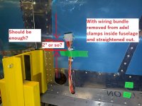
This thread raised a lot of awareness with me and @wirejock, thanks for pointing out there will only be about an inch of service access here!  My nearly full 15 pin connector is 0.75" wide. I will need a very narrow securing bracket solution with top-access. Though it is debatable if I am using the correct connector type here(perhaps a new never ending debate subject?), I am doing my wire runs in such a way that I can change this, maybe even before it flies...
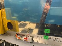
The wires add up fast (I moved the hole slightly to accommodate a slightly larger diameter), and I'll need about as many wires on the other side! (Servo instead of magnetometer...) Even on this side: Magnetometerx3, (under)wing analog video looking at ldg gear/prop, 12v for wing cam, 2xpitot power, flyLED nav/strobes(at end of connector and sheilded from the rest) need 4 wires, LH LDG light PWR, LH TAXI light PWR, Fuel Qty Resistance. Not done wiring so I might have even missed something! Also, even with the sheilding/pin distance precautions taken, I am curious if all of this can be shared on the same connector without interference... TBA...
My nearly full 15 pin connector is 0.75" wide. I will need a very narrow securing bracket solution with top-access. Though it is debatable if I am using the correct connector type here(perhaps a new never ending debate subject?), I am doing my wire runs in such a way that I can change this, maybe even before it flies...The wires add up fast (I moved the hole slightly to accommodate a slightly larger diameter), and I'll need about as many wires on the other side! (Servo instead of magnetometer...) Even on this side: Magnetometerx3, (under)wing analog video looking at ldg gear/prop, 12v for wing cam, 2xpitot power, flyLED nav/strobes(at end of connector and sheilded from the rest) need 4 wires, LH LDG light PWR, LH TAXI light PWR, Fuel Qty Resistance. Not done wiring so I might have even missed something! Also, even with the sheilding/pin distance precautions taken, I am curious if all of this can be shared on the same connector without interference... TBA...
Attachments
Thanks, indeed it isMaybe different on your bird, but on my 7A, the fuel sender (capacitive) is on the forward side of the wing spar.
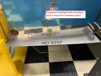
 Nice to have relevant VAF threads up in the shop while I work. Better than AI ! Cost me 2 zip ties but it's now moved
 ")
Well, I really don’t know what caused it. In both instances I did continuity checks from the instruments to the connector. Then from the connector to the magnetometer and the roll servo. Continuity was good in all directions from the connector(s) with it unplugged. When I plugged the connector(s) back in, no continuity. At that point I pulled out my wire cutters in both instances and cut all the wires to the connector(s) and replaced the magnetometer wiring with the round d-sub connector that has a positive screw on connector. On the wiring for the roll servo, the bad connection was for the wire for the termination of the can bus. For that group of wires I used butt splices to connect all the wires running out from the fuselage to the roll servo.Just for my own learning purposes, what happened? Was it a crimp failure or contamination/corrosion within the connection itself?
