
Van's Air Force
You are using an out of date browser. It may not display this or other websites correctly.
You should upgrade or use an alternative browser.
You should upgrade or use an alternative browser.
Service Bulletin 12-11-09 (Main Landing Gear Upgrade)
- Thread starter Tony_T
- Start date

Next question is how to drain the brake lines so they can be disconnected without dripping fluid inside the fuselage.
The process described in the S.B. instructions actually works quite well.....
LittleJoeA
Well Known Member
SB 12-11-09 Posted
The 30 page SB 12-11-09 is now posted on Van's web site.
http://www.vansaircraft.com/pdf/sb12-11-09.pdf
I am right at the point where I was going to attach the landing geat and of course I'm waiting for the upgrade kit. Maybe in time for a Christmas present.
The 30 page SB 12-11-09 is now posted on Van's web site.
http://www.vansaircraft.com/pdf/sb12-11-09.pdf
I am right at the point where I was going to attach the landing geat and of course I'm waiting for the upgrade kit. Maybe in time for a Christmas present.
The 30 page SB 12-11-09 is now posted on Van's web site.
I can't see any mention in the SB 12-11-9 documentation about the slight step that I and a number of others have reported at the inner edge of the cutout in the channel for the AN5-22A attach bolts. The step prevents the washer under the nut from bearing uniformly against the flat face of the channel. Is this not considered to be a problem?
I raised this with Vans some time ago and was told to file it flat, but that is simply not practical in the confined space available, and certainly not with any accuracy.
Step in C-Section Observations
It is my understanding that the SB fix has taken the "step" issue out of the problem. It is also (IMHO) why the doublers are located on the bottom of the C-Section instead of the top of the C-Section which would have been an easier installation. I have noticed from the photos of C-Section cracks (Fig 16 of the SB for example) that all of them appear to have a "step" in the bolt hole cut-out area. I have a step at all 4 bolt hole cut-outs and have 2 cracks at the right forward bolt hole and 1 crack at the left forward bolt hole. The "step" may not be the only reason that some of us have cracks but I do believe that it is a significant contributor to our landing gear damage. Maybe a "structures guy" could comment on my speculation. I have received the SB Kit and it looks stout! Bob Kibby "N712BK"
It is my understanding that the SB fix has taken the "step" issue out of the problem. It is also (IMHO) why the doublers are located on the bottom of the C-Section instead of the top of the C-Section which would have been an easier installation. I have noticed from the photos of C-Section cracks (Fig 16 of the SB for example) that all of them appear to have a "step" in the bolt hole cut-out area. I have a step at all 4 bolt hole cut-outs and have 2 cracks at the right forward bolt hole and 1 crack at the left forward bolt hole. The "step" may not be the only reason that some of us have cracks but I do believe that it is a significant contributor to our landing gear damage. Maybe a "structures guy" could comment on my speculation. I have received the SB Kit and it looks stout! Bob Kibby "N712BK"
Dgamble
Well Known Member
Page 16 of 30
Step 32: Add bevels to the four corners of the U-1202 Outboard Main Gear Attach Brackets.
Has anyone done this yet, and if so, how? My first inclination is to take the grinding wheel to it, but my first inclination is almost always wrong.
Problem here is that I don't have a Plan B.
Step 32: Add bevels to the four corners of the U-1202 Outboard Main Gear Attach Brackets.
Has anyone done this yet, and if so, how? My first inclination is to take the grinding wheel to it, but my first inclination is almost always wrong.
Problem here is that I don't have a Plan B.
Gagarin737
Well Known Member
I taped off the 1/4" and used a grinding wheel. I polished the corners with a file and the scotch brite wheel.
Step 32: Add bevels to the four corners of the U-1202 Outboard Main Gear Attach Brackets.
Has anyone done this yet, and if so, how? My first inclination is to take the grinding wheel to it, but my first inclination is almost always wrong.
Problem here is that I don't have a Plan B.
A somewhat course belt (60 - 80 grit) on a belt sander will work quite well (if you are not in a huge hurry). Have a container of water to dip the parts in occasionally to keep them from getting excessively hot.
It is my understanding that the SB fix has taken the "step" issue out of the problem. It is also (IMHO) why the doublers are located on the bottom of the C-Section instead of the top of the C-Section which would have been an easier installation. I have noticed from the photos of C-Section cracks (Fig 16 of the SB for example) that all of them appear to have a "step" in the bolt hole cut-out area. I have a step at all 4 bolt hole cut-outs and have 2 cracks at the right forward bolt hole and 1 crack at the left forward bolt hole. The "step" may not be the only reason that some of us have cracks but I do believe that it is a significant contributor to our landing gear damage. Maybe a "structures guy" could comment on my speculation. I have received the SB Kit and it looks stout! Bob Kibby "N712BK"
That's what I was expecting, but I can't get my fuzzy "structures" head around how this takes the step issue out of it (home with the flu).
 I'll go back and have another look.
That's what I was expecting, but I can't get my fuzzy "structures" head around how this takes the step issue out of it (home with the flu).
The information I have is that of the airplanes that did have any evidence of cracks, only one of those had any amount of step at the bolt locations (and then only on one side).
The photo of crack damage included in the S.B. document is not of a center section with a step. You can clearly see a imprint mark left by the full circumference of the washer.
The step is not being considered a factor considering the known loads and the testing results. This is particularly the case, after the S.B. modification has been installed.
As the S.B. states, all indicators are that the airplanes that received damage was because of excessively loose bolts, probably stemming from inadequate torque / stretch pre-load at installation (The reason the installation process has been changed, and the PAP amended to require re-torquing the bolts after completing the flight test period).
Last edited:
DonFromTX
Well Known Member
My "steps" are of different dimensions on all four holes. I am considering putting a washer in my mill, and machining off the exact amount of the step. Something to do while I am waiting for my kit and it will make me feel better I suppose. I can agree that the step is probably insignificant in terms of causing a problem, as Scott said, the photo in the SB shows fairly severe cracking and yet the washer obviously was laying flush..
yankee-flyer
Well Known Member
Brake fluid
Thanks Tony,
Nice to know that! Yep, I used the right stuff. 93 Octane UL does take Imron off, though-- some how cuts through the epoxy primer and then blisters the paint!!
Wayne
Thanks Tony,
Nice to know that! Yep, I used the right stuff. 93 Octane UL does take Imron off, though-- some how cuts through the epoxy primer and then blisters the paint!!
Wayne
tim walter
Well Known Member
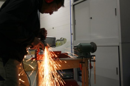
grind the bevels
yes a grinder works great.
they parts get hot easily taking off that much material,
so go slow, I didn't quench mine because I didn't want any hardening of the material, I just did it slow.
then polish with scotchbrite prime and paint
http://2.bp.blogspot.com/-GH07KTZ49YQ/UHUK_e8IaII/AAAAAAAAAWE/hwgKOamWej8/s1600/IMG_6649.jpg
Step 32: Add bevels to the four corners of the U-1202 Outboard Main Gear Attach Brackets.
Has anyone done this yet, and if so, how? My first inclination is to take the grinding wheel to it, but my first inclination is almost always wrong.
Problem here is that I don't have a Plan B.
yes a grinder works great.
they parts get hot easily taking off that much material,
so go slow, I didn't quench mine because I didn't want any hardening of the material, I just did it slow.
then polish with scotchbrite prime and paint
http://2.bp.blogspot.com/-GH07KTZ49YQ/UHUK_e8IaII/AAAAAAAAAWE/hwgKOamWej8/s1600/IMG_6649.jpg
tim walter
Well Known Member
fix for the channel "step"
It looks like F1204V fixes the step by laying flat over it
can someone who actually has the kit confirm that?
It is my understanding that the SB fix has taken the "step" issue out of the problem. It is also (IMHO) why the doublers are located on the bottom of the C-Section instead of the top of the C-Section which would have been an easier installation. I have noticed from the photos of C-Section cracks (Fig 16 of the SB for example) that all of them appear to have a "step" in the bolt hole cut-out area. I have a step at all 4 bolt hole cut-outs and have 2 cracks at the right forward bolt hole and 1 crack at the left forward bolt hole. The "step" may not be the only reason that some of us have cracks but I do believe that it is a significant contributor to our landing gear damage. Maybe a "structures guy" could comment on my speculation. I have received the SB Kit and it looks stout! Bob Kibby "N712BK"
It looks like F1204V fixes the step by laying flat over it
can someone who actually has the kit confirm that?
It looks like F1204V fixes the step by laying flat over it
can someone who actually has the kit confirm that?
Bob Kibby does indeed have the kit.
It looks like F1204V fixes the step by laying flat over it
can someone who actually has the kit confirm that?
The F-1204V is not an added part, it is a drill template used in preparation for installing the parts.
The step by step instructions explain its use on page 17.
tim walter
Well Known Member
The F-1204V is not an added part, it is a drill template used in preparation for installing the parts.
The step by step instructions explain its use on page 17.
yes I see that now.
oh well, Vans must not be concerned with the step
I personally think it should be flat, they should certainly think about refining the design there.
I might try and file mine flatter, maybe with a dremel I can make a circular flat spot for the washer....
No way...
No Way Tim, should you attempt to re-machine the center section by hand with a dremel tool. Consider the consequences if you muck it up.
Please re-read post #61. Van's has done the engineering, the testing, and designed a fix that in their own words (in post #61 and an email to me in response to a picture I sent them) makes the step a non-issue.
It's not like it got little attention, this took them weeks of resources. I don't understand why folks are having such a hard time believing them on this matter .
.
Tony
No Way Tim, should you attempt to re-machine the center section by hand with a dremel tool. Consider the consequences if you muck it up.
Please re-read post #61. Van's has done the engineering, the testing, and designed a fix that in their own words (in post #61 and an email to me in response to a picture I sent them) makes the step a non-issue.
It's not like it got little attention, this took them weeks of resources. I don't understand why folks are having such a hard time believing them on this matter
.Tony
As Tony said...
Vans were aware of the step when they did their investigation and clearly don't consider that it needs any correction. If you try to remove it, you are more likely to create a problem. In fact, the plus side of having a step is that you have a little extra thickness in that area to distribute the bolt tension, and that's not a bad thing.
Vans were aware of the step when they did their investigation and clearly don't consider that it needs any correction. If you try to remove it, you are more likely to create a problem. In fact, the plus side of having a step is that you have a little extra thickness in that area to distribute the bolt tension, and that's not a bad thing.
joedallas
Well Known Member
OK AS IS
Robert
I see this in a different view
The high point narrows the point load and increases the shear potential
However van's has solved this problem by adding a bolt at each side to share the tension and move it to the flange of the U-Chanel.
So I agree Vans were aware of the step when they did their investigation and clearly don't consider that it needs any correction.
Vans were aware of the step when they did their investigation and clearly don't consider that it needs any correction. If you try to remove it, you are more likely to create a problem. In fact, the plus side of having a step is that you have a little extra thickness in that area to distribute the bolt tension, and that's not a bad thing.
Steps amd cracks
For RV2002Builder, I have steps at all 4 outboard bolt hole locations and I have 2 cracks on the right side forward hole and 1 crack on the left side forward hole. There was no washer contact from the bolt hole to the flat part of the C-section at any of the 4 bolt hole locations.
As Peterk posted I have the kit and have started the repair. I have done a fit check of all the parts and everything fits very well. A slight interference between the forward part of left hand saddle and a rivet which was identified as a possibility in the SB for earlier kits. With help, we have straightened out the wrinkles and clecoed the doublers in place. All the current holes line up without any problem and the doubler pulls up tight against the existing skin without any visible gaps.
Glad to see some light at the end of the tunnel. Even our Texas weather is cooperating so working conditions at the hangar are comfortable. Bob Kibby N712BK "still on injured reserve but recovering"
Robert
I see this in a different view
The high point narrows the point load and increases the shear potential
However van's has solved this problem by adding a bolt at each side to share the tension and move it to the flange of the U-Chanel.
Yes, the front half of the doubler is basically beefing up the channel web and helping to spread the concentrated load from the problematic front bolt more efficiently, and generally reduce stresses. Roughly the same as if the web in that area was thicker to start with. It's also providing more bearing area for the AN5 bolt shank, but that's probably a secondary consideration. The aft part of the doubler is mainly along for the ride, because that's not where the problem is.
Anyway, that's just my interpretation, and I don't want to hijack the thread. I'm happy to leave all the analysis to the real aeronautical engineers at Vans and see how Tony progresses with his installation. Just waiting for my parts to arrive now, so I can do the same. It's also clear from looking through the documentation that this exercise took a LOT of engineering time, effort and money, so thanks again to Vans and to Scott for all his input.
") .
.Vans were aware of the step when they did their investigation and clearly don't consider that it needs any correction. If you try to remove it, you are more likely to create a problem. In fact, the plus side of having a step is that you have a little extra thickness in that area to distribute the bolt tension, and that's not a bad thing.
The bigger question for Vans is why is there variation in these hole pockets? Some have no steps, and those that have steps, have steps of varying dimensions. For a machining operation on a piece of Primary structure, this is clearly unacceptable. Very hard for me to fathom how this could happen in the first place, and also how it could pass post-machining inspection. This variability makes defining the problem and the solution that much more difficult.
And yes, I say this (reluctantly) as having been Director of Quality Assurance for 10 years at Boeing Commercial Airplanes.
I myself wouldn't touch adjusting the step with a ten foot pole.
Bob Bogash
N737G
The center section C channel on an RV-12 is made from an aluminum extrusion.
When you purchase raw aluminum extrusion, the specified dimensional tolerances provided by the manufacturer are quite large (at least compared to rolled aluminum sheet stock).
The channel would have been prohibitively expensive if every single part received surface milling on all sides during production.
Consequently, when the pockets are milled using the bottom surface as a zero reference, any variation in the extruded thickness will cause an equal variation in the pocket alignment.
It can not be said for certain that this explains 100 % of the dimensional variation at the bottom of the pocket, but it is certainly a lot of it.
For RV2002Builder, I have steps at all 4 outboard bolt hole locations and I have 2 cracks on the right side forward hole and 1 crack on the left side forward hole.
I stand corrected.
I rechecked my information and found that their was only one airplane that had aggresive cracks that required an additional re-enforcement (beyond what the S.B. provides), where there was also a step.
There was no washer contact from the bolt hole to the flat part of the C-section at any of the 4 bolt hole locations.
By flat part, I assume you mean the main web of the C channel, because even if there is a step at the pocket location, there is still a flat at the bottom of the milled pockets at the location of each bolt hole. Just in some cases it is not as large as the full foot print of the washer (but it still is flat).
Just to reiterate...
A stepped surface under the washer had nothing to do with cracks in the channel. The cracks were caused by excessively loose bolts. Most of the airplanes that have any cracks, had no steps under the washers. In some of these cases, the washer pounded a recessed depression into the C channel (because the bolt was loose).
Received my SB kit today.
Inventoried, it's all there. Congrats and thanks to everyone at Van's for providing what appears to be a well engineered improvement. Sure is nice to get such a complete package, so we don't have to chase down the necessary parts on our own.
Serial # 176, about 100th to fly.
Inventoried, it's all there. Congrats and thanks to everyone at Van's for providing what appears to be a well engineered improvement. Sure is nice to get such a complete package, so we don't have to chase down the necessary parts on our own.
Serial # 176, about 100th to fly.
JB finishes upgrade w/picture album
JBs completed upgrade:

John Bender completed his SB 12-11-09 MLG Upgrade and has posted a picture album in Piccasa:
http://www.vansairforce.com/community/showpost.php?p=721630&postcount=98
John,
Hope you don't mind, a post in this thread will lead searchers for SB 12-11-09 to your pictures.
Tony
JBs completed upgrade:
John Bender completed his SB 12-11-09 MLG Upgrade and has posted a picture album in Piccasa:
http://www.vansairforce.com/community/showpost.php?p=721630&postcount=98
John,
Hope you don't mind, a post in this thread will lead searchers for SB 12-11-09 to your pictures.
Tony
No problem Tony - -
I just stopped once in a while and took a picture. I was hoping it would give a better idea of the size of the job. I worked very hard at it. Lots of drilling and riveting. I have a small compressor at the airport, and used the rivet gun that came with my tool kit. Glad I had it.
John Bender
I just stopped once in a while and took a picture. I was hoping it would give a better idea of the size of the job. I worked very hard at it. Lots of drilling and riveting. I have a small compressor at the airport, and used the rivet gun that came with my tool kit. Glad I had it.
John Bender
Is there anyone in the Salem, OR area, who has received this kit but does not plan to do the modification for a couple of months, who would be willing to trade for my future kit? According to Vans, I should receive my kit by Jan. 11. They estimated 25-40 days and that was Nov. 27.
I have just started my fuse sub-kit and am starting to need some of the new pieces.
Anyone able to do this please send a PM. Thanks in advance.
I have just started my fuse sub-kit and am starting to need some of the new pieces.
Anyone able to do this please send a PM. Thanks in advance.
The purpose of the fuel tank mod is to prevent the tank from rupturing in the event of a crash. The purpose of the more robust landing gear upgrade is to prevent damage during normal takeoff and landing, not during crashes. No matter how strong the landing gear is, in the event of a forced off airport landing, the landing gear will bend if it strikes an object like a rock or tree stump or ditch or etc. And then the fuel tank will rupture if it has not been reinforced per the service bulletin. The pilot who crashed and was sprayed with fuel was lucky that there was no fire. Others might not be so lucky.
Modifying the fuel tank and working with tank sealant is not fun work. But the pilot and passenger will be thankful the fuel tank did not rupture as they walk away unscathed from the crash site.
Joe Gores
Modifying the fuel tank and working with tank sealant is not fun work. But the pilot and passenger will be thankful the fuel tank did not rupture as they walk away unscathed from the crash site.
Joe Gores
I plan to do SB 12-11-09 completely, when my parts arrive. I did not do the fuel tank mod, and am considering not doing it, now that we have a much more robust MLG system. Oh, I'm building it under the EAB rules.
Any thought!!
Tom
Tom, Joe is right. IMHO it would be very shortsighted not to install the fuel tank mod. It is not that big of a deal, especially if done concurrently with the MLG SB.
tim walter
Well Known Member
JBs completed upgrade:
John Bender completed his SB 12-11-09 MLG Upgrade and has posted a picture album in Piccasa:
http://www.vansairforce.com/community/showpost.php?p=721630&postcount=98
John,
Hope you don't mind, a post in this thread will lead searchers for SB 12-11-09 to your pictures.
Tony
I notice that you have tucked the brake line under the main gear leg.
I was thinking about that myself, after seeing the photos of damaged brake lines.
But is there any chance the brake line could contact the lower skin cover?
Geico266
Well Known Member
to be honest, I just put it there cause it worked. It is behind the leg until it goes into the fuse. Photo may be deceiving.
John Bender
Nice work John.

Cherry Max rivets are a chore. They manufacturer calls out using buying or renting their gun.
Last edited:
SB 12-11-09
Thanks to Tony T for the new thread. I'm glad to see Van's is "comp"ing the kit. Is there a delay for shipping. I will order ASAP.
Although I see this is quite a project for flying RV-12s, I'm bummed because I JUST finished landing gear, bleeding the brakes, fuel tank & ELT. At least my wings are off (no wing root seals yet, either), no fuel in the tank. Any guesses yet on how long to complete? The SB is 30 pages; a bit daunting!
JRo
Finish kit & Avionics in progress
N448JR reserved
SB kit
There is no need to order the kit- it is being shipped automatically at no cost to everyone. As I understand from prior messages, they are prioritizing flying aircraft first and then builders who have received finishing kits. I received mine last Saturday.
Jeff
Thanks to Tony T for the new thread. I'm glad to see Van's is "comp"ing the kit. Is there a delay for shipping. I will order ASAP.
There is no need to order the kit- it is being shipped automatically at no cost to everyone. As I understand from prior messages, they are prioritizing flying aircraft first and then builders who have received finishing kits. I received mine last Saturday.
Jeff
GEICO266 mentioned cherry rivets. I haven't got my kit yet. Are they cherry rivets? I really don't want to have to buy an expensive cherry rivet puller!
GEICO266 mentioned cherry rivets. I haven't got my kit yet. Are they cherry rivets? I really don't want to have to buy an expensive cherry rivet puller!
The kit uses a Cherry rivet that can be pulled with a standard blind rivet tool. You should be able to use the same puller tool(s) that were used to build the airplane
Geico266
Well Known Member
GEICO266 mentioned cherry rivets. I haven't got my kit yet. Are they cherry rivets? I really don't want to have to buy an expensive cherry rivet puller!
Some of the rivets are Cherry Max. I found out today that a regular puller MAY work, but the Avery puller will not. The stems (mandrels) are too short. Thanks to Bobby K & John Bender I tried another puller I had and it worked fine.
Last edited:
P
paul mosher
Cherry
I have pulled -6 cherry max rivets with the harbour freight puller.
I have pulled -6 cherry max rivets with the harbour freight puller.
txaviator
Well Known Member
Kits are now being received by those with non-flying aircraft.
That's excellent news! Thanks for posting the update. I'm kit #610, so hopefully I will receive it shortly...otherwise, a lot of the finish kit is on hold!
Paul LeDoux
Active Member
I also know the waiting game. My kit is S/N RV120495, It is also stalled in the Finish Kit stage. I am waiting on the Avionics also.
Paul Ledoux
Paul Ledoux
SB kits are a comin'...
Talked with Van's late Friday afternoon and was informed that all SB kits will be shipped next week (hopefully by Wednesday) to flying aircraft and those who have finish kits! In the end, Van's will ship approximately 200 SB kits at no charge... now that's CUSTOMER SERVICE at the highest level. Thanks Van's!
Talked with Van's late Friday afternoon and was informed that all SB kits will be shipped next week (hopefully by Wednesday) to flying aircraft and those who have finish kits! In the end, Van's will ship approximately 200 SB kits at no charge... now that's CUSTOMER SERVICE at the highest level. Thanks Van's!
Last edited:
FWIW - A neighbor with kit 169 got his yesterday and mine (kit279) came today. We both have finish kits. Kits are coming without the wing root seal which is backordered to 12/16. Not a big deal for my stage.
Another neighbor with a flying -12 is about done with the modification and figures he will have less than 40 hours in it. His is unpainted so that saved him a little time.
Another neighbor with a flying -12 is about done with the modification and figures he will have less than 40 hours in it. His is unpainted so that saved him a little time.
