Building a forward induction angle valve io-360 with the VA-132 snorkle.

 store.vansaircraft.com
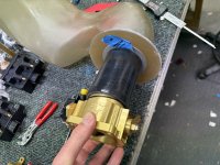
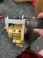
Using SDS with the short throttle body.
Was wondering if anyone had any photos of how you modified your snorkle to adapt to the throttle body?
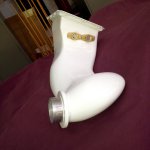
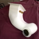
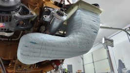
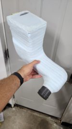
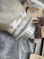
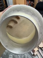
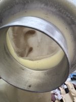
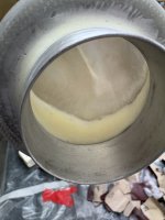
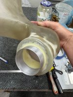
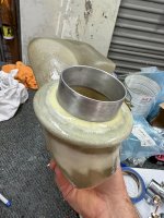
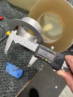
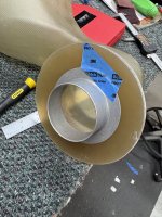
I have a 2.5” aluminium flange. I was thinking of just epoxying it on, then glassing around the flange. Work out the fore aft position by trimming the silicone hose.
Best I can work out is the RSA-5 the standard snorkle is designed to mate with is 5.5” long. The SDS throttle body is only 2.6” long. So I have some good room to play with fore/aft.
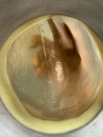
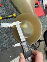
The only issue I see is the internal diameter of the snorkle is 3”, whereas the internal of the aluminium adapter is 2.35. So I guess I should build a ramp on the inside with micro or something to smooth it out. Not sure a 90 degree flange is a smart idea? Probably needs to be smoothed out.
Some photos attached for reference.
Fiberglass Snorkel, Horizontal Induction
The VA-132-2 snorkel is designed to be used with horizontal induction angle valve IO-360 engines, with a lightweight Skytec starter, and fuel servo Bendix clones (AVSTAR, Precision Airmotive) VA -132-2 will not work with FM-150C Airflow Performance throt
Using SDS with the short throttle body.
Was wondering if anyone had any photos of how you modified your snorkle to adapt to the throttle body?
I have a 2.5” aluminium flange. I was thinking of just epoxying it on, then glassing around the flange. Work out the fore aft position by trimming the silicone hose.
Best I can work out is the RSA-5 the standard snorkle is designed to mate with is 5.5” long. The SDS throttle body is only 2.6” long. So I have some good room to play with fore/aft.
The only issue I see is the internal diameter of the snorkle is 3”, whereas the internal of the aluminium adapter is 2.35. So I guess I should build a ramp on the inside with micro or something to smooth it out. Not sure a 90 degree flange is a smart idea? Probably needs to be smoothed out.
Some photos attached for reference.
")